
Sensorless compound control method for permanent magnet synchronous motor

A technology of permanent magnet synchronous motor and compound control, which is applied in motor control, motor generator control, electronic commutation motor control, etc., to achieve strong anti-interference and wide adaptability

Inactive Publication Date: 2018-09-28
WUHAN UNIV OF TECH
View PDF4 Cites 6 Cited by
  • Summary
  • Abstract
  • Description
  • Claims
  • Application Information

AI Technical Summary

Problems solved by technology

However, there is currently no sensorless control method that can run stably in the full speed range. In the zero and low speed ranges, high frequency injection and other methods are usually used, and in the medium and high speed ranges, sliding mode observers and EKF observers are usually used. and other methods, the traditional sliding mode observer has strong robustness to parameter changes, but it will inevitably bring chattering and time delay problems, while the EKF observer is suitable for high-performance servo systems, which can work in the range, and can also estimate related states and certain parameters

Method used


Image

  • Sensorless compound control method for permanent magnet synchronous motor
  • Sensorless compound control method for permanent magnet synchronous motor
  • Sensorless compound control method for permanent magnet synchronous motor

Examples


Embodiment Construction

[0038] Embodiments of the present invention will be described in detail below in conjunction with the accompanying drawings.

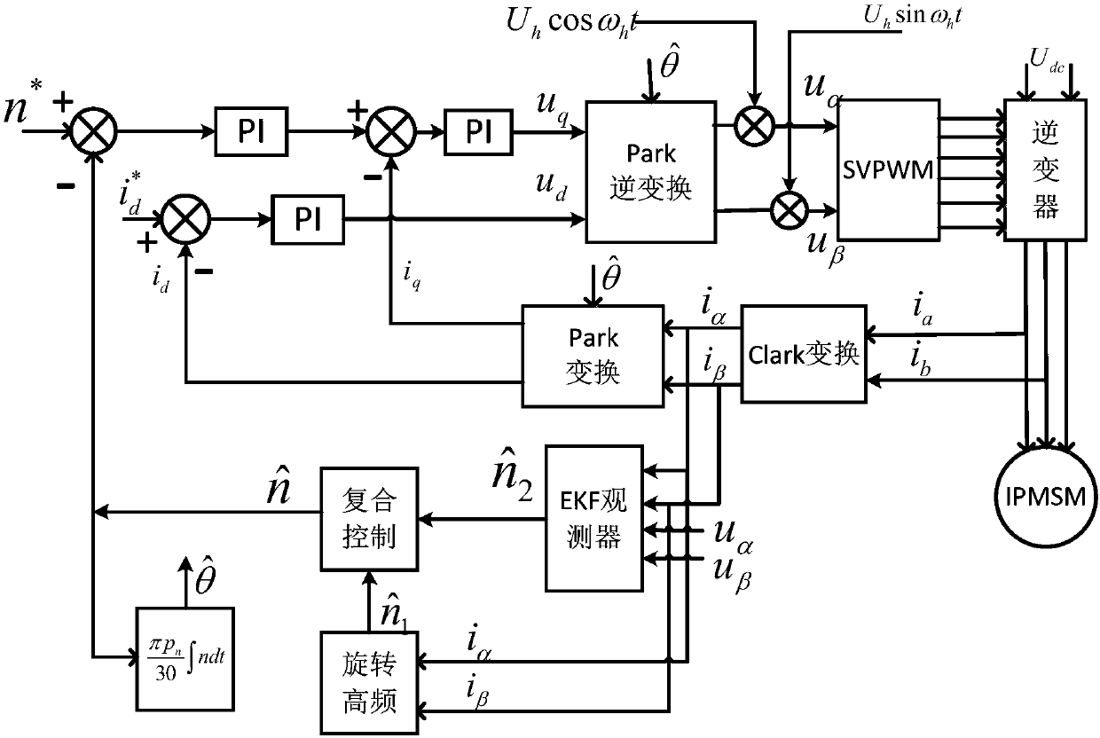
[0039] This embodiment is achieved through the following technical solutions. A sensorless composite control method for a permanent magnet synchronous motor is used to control a permanent magnet synchronous motor, comprising the following steps:

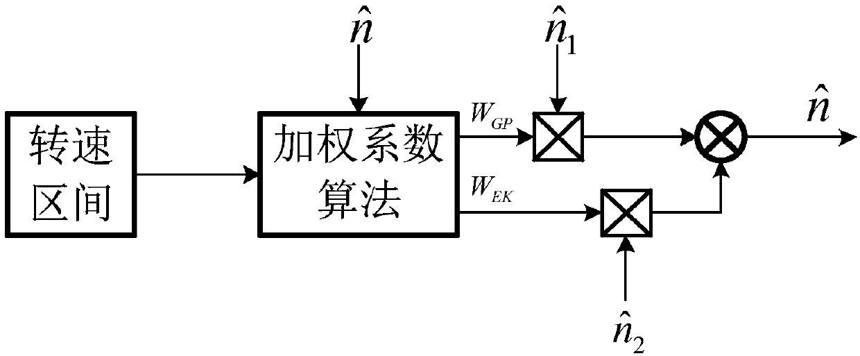
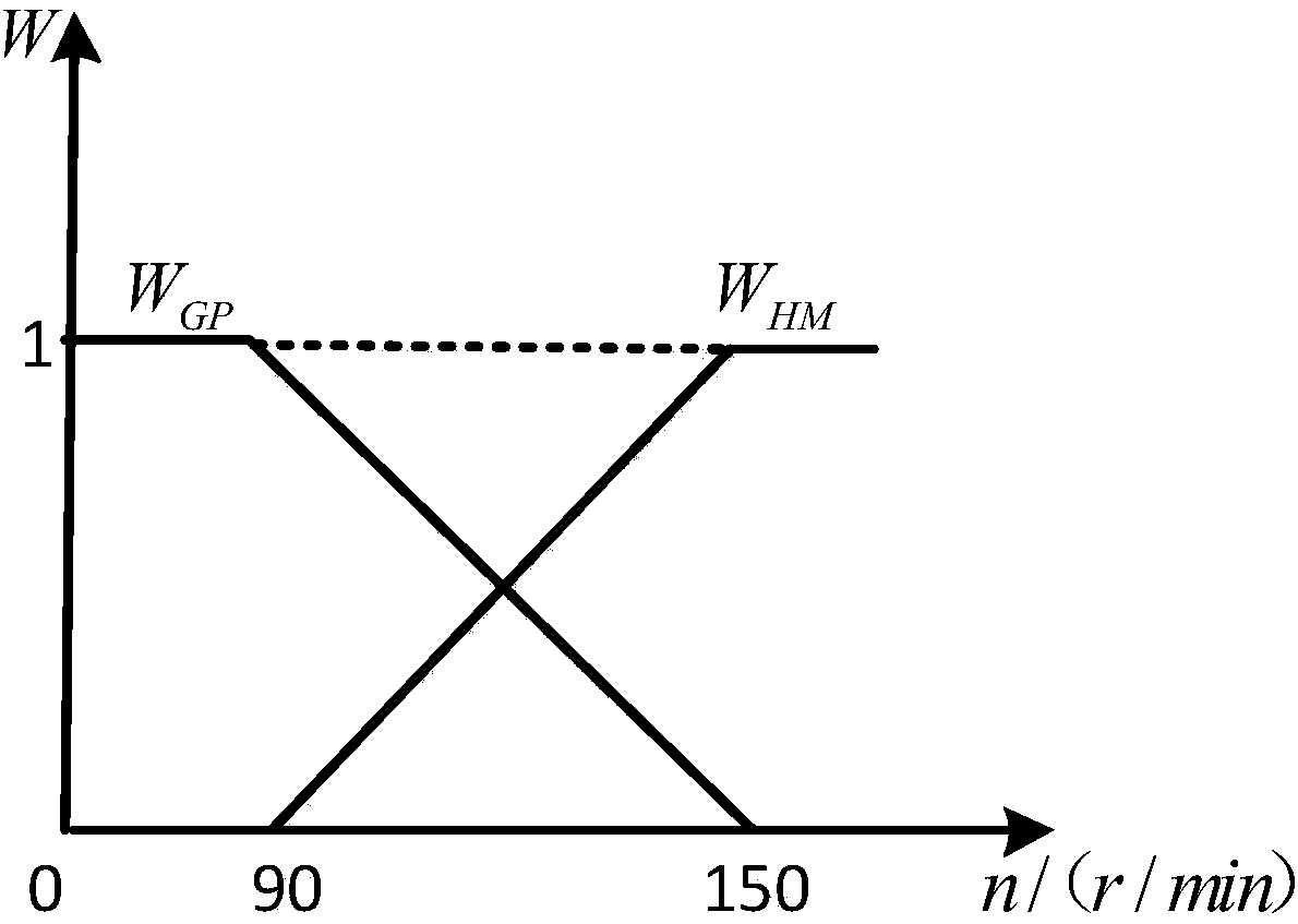
[0040] The sensorless control of the permanent magnet synchronous motor adopts the compound control method, and the control process is divided into three stages according to the output speed value calculated by the compound control: the first stage is zero, the low speed stage, and the upper limit of the speed is n min , this stage adopts the rotating high-frequency voltage injection method to detect the speed and rotor position; the second stage is the transition stage, and the upper and lower limits of the speed are respectively n max , n min , this stage adopts the composite control method to detect the s...


PUM


Abstract

The invention belongs to the technical field of permanent magnet synchronous motors and in particular relates to a sensorless compound control method for a permanent magnet synchronous motor, comprising the following steps: firstly, according to a rotating speed output after compound control computation, dividing a control process into a first stage, a second stage and a third stage, wherein the first stage is a zero-and-low speed stage, the upper limit value of the rotating speed of the first stage is nmin, the second stage is a transition stage, the upper and lower limits of the rotating speed of the second stage are nmax and nmin respectively, the third stage is a medium-and-high speed stage, and the lower limit of the rotating speed of the third stage is nmax; secondly, detecting the rotating speed and a position of a rotor by adopting a rotary high frequency voltage injection method in the zero-and-low speed stage; thirdly, detecting the rotating speed and the position of the rotor by adopting a compound control method in the transition stage; and fourthly, detecting the rotating speed and the position of the rotor by adopting an EKF observer method in the medium-and-high speed stage. The method can realize sensorless control on the permanent magnet synchronous motor in full speed range and has the advantages of wide application range and strong resistance to interference.

Description

technical field [0001] The invention belongs to the technical field of permanent magnet synchronous motors, in particular to a sensorless composite control method for permanent magnet synchronous motors. Background technique [0002] Permanent magnet synchronous motor (PMSM) has become a research hotspot and has been widely used due to its simple structure, stable speed, fast dynamic response, strong overload capacity, high reliability, diverse structure, and wide application range. [0003] The traditional permanent magnet synchronous motor mechanical speed position sensor not only increases the cost, volume and installation difficulty of the motor system, but also has strict requirements on the environment, and the measurement accuracy is easily affected by vibration, which reduces the overall reliability of the system. The PMSM drive system using sensorless control technology can improve operating efficiency, expand the scope of use, reduce equipment costs and operating c...

Claims


Application Information

Patent Timeline
IPC IPC(8): H02P21/24H02P21/00H02P21/04H02P21/18H02P21/13
CPCH02P21/24H02P21/0085H02P21/04H02P21/13H02P21/18H02P2203/03H02P2203/09H02P2207/05
Inventor 胡红明方贺肖寒刘雪骄
Owner WUHAN UNIV OF TECH
Learn More