Method and system for reducing interference caused by phase noise in radar system

A phase noise, radar system technology, applied in the radio wave measurement system, the use of re-radiation, the reflection/re-radiation of radio waves, etc., can solve the problems of reducing accuracy and range, interference, and high computational cost, achieving low computational cost, Influence of suppression, effect of suppression of phase noise/phase noise

Active Publication Date: 2018-09-28
SYMEO
View PDF23 Cites 4 Cited by
  • Summary
  • Abstract
  • Description
  • Claims
  • Application Information

AI Technical Summary

Problems solved by technology

[0007] In the prior art, especially in signals with multiple signal components, i.e. with multiple targets or multiple signal tr

Method used


Image

  • Method and system for reducing interference caused by phase noise in radar system
  • Method and system for reducing interference caused by phase noise in radar system
  • Method and system for reducing interference caused by phase noise in radar system

Examples


Embodiment Construction

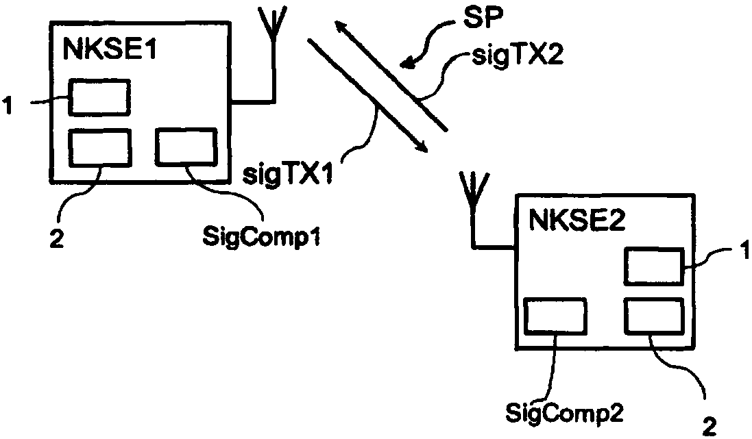
[0048] as from figure 1 It can be seen that the two sending and receiving units NKSE1 , NKSE2 communicate with each other via the radio interface. Here, the first or second signal sigTX1, sigTX2 is transmitted. The transmitting and receiving units NKSE1, NKSE2 each have a signal source 1, a unit 2 for clock matching or comparison signal modulation and a transmitting comparison unit (SigComp1, SigComp2).

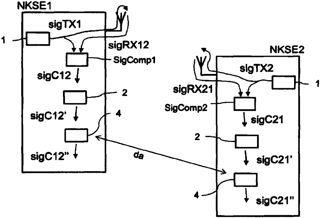
[0049] figure 2 In addition, units for phase modulation 4 are shown in each case. Data exchange takes place between the two units for phase modulation 4 .

[0050] Next, a precise mathematical derivation according to the invention is carried out. In a first non-coherent transmit and receive unit (NKSE1), a first signal (sigTX1) is generated and transmitted, in particular transmitted, via a path (SP). In a further transmission and reception unit, in particular a second non-coherent transmission and reception unit (NKSE2), a second signal (sigTX2) is generated and sent, ...


PUM


Abstract

A method for reducing interference caused by phase noise in a radar system is described in particular, in which a first signal (sigTX1) is generated in a first non-coherent transceiving unit (NKSE1) and is transmitted, in particular emitted, via a path (SP), a first signal (sigTX2) is generated in a further, in particular second non-coherent transceiving unit (NKSE2) and is transmitted, in particular emitted, via the path (SP), the signals (sigTX1 and sigTX2) are directly or indirectly received in the respective other transceiving stations and are processed there as reception signals sigRX12 and sigRX21, a comparison signal (sigC12) is formed in the first transceiving unit (NKSE1) from its first signal (sigTX1) and from such a first signal (sigTX2) received from the further transceiving unit (NKSE2) via the path (SP), and a further comparison signal (sigC21) is formed in the further transceiving unit (NKSE2) from its first signal (sigTX2) and from such a first signal (sigTX1) receivedfrom the first transceiving unit (NKSE1) via the path (SP), wherein the further comparison signal (sigC21) is transmitted, in particular communicated, from the further transceiving unit (NKSE2) to thefirst transceiving unit (NKSE1), wherein in a first step deviations of the signals sigC21 and sigC12 which are caused by systematic deviations in the transceiving units (NKSE2, NKSE1) are compensatedfor, wherein in a second step at least one complex value from a first of the two comparison signals or from a signal which has been derived from this first comparison signal is used to adapt at leastone complex value of the second of the two comparison signals or a value of a signal which has been derived from this second comparison signal and to therefore form a signal (sigCC), wherein the adaptation is carried out using a mathematical operation to form the vectorial sum or the difference of the complex values or the sum or the difference of the phases of the complex values.

Description

technical field [0001] The invention describes a method for processing radio signals which are transmitted, in particular emitted, by at least two unrelated transmitting and receiving devices NKSE1 and NKSE2 and are each passed on to a further NKSE and received there. In this case, the at least two transmitting and receiving devices are associated with at least partially independent devices (signal sources) for generating signals. The independent signal generation has the effect that the generated signals of the different NKSEs initially do not have a defined phase correlation with one another, ie are not coherent with one another. Background technique [0002] In this case, a distributed radar system can be a system with at least two NKSEs, between which the signals are connected indirectly (reflection at objects, scatterers or boundary layers) or directly (via line-of-sight propagation) from at least one sender to at least one receiver. A radar network can be used to map...

Claims


Application Information

Patent Timeline
IPC IPC(8): G01S7/40G01S13/87
CPCG01S7/4021G01S13/878G01S7/354
Inventor M·福西克M·戈廷格F·基尔施P·古尔登
Owner SYMEO
Why Eureka
Try Eureka