
Fillet system for valve stem

A technology of guide fillet and valve stem, which is applied in the field of valve production equipment and valve stem guide fillet system, which can solve the problems of reducing work efficiency, waste of resources, and low work efficiency, so as to improve work efficiency and reduce labor intensity , the effect of convenient operation

Pending Publication Date: 2018-10-02
天津市莱斯特阀门有限公司
View PDF0 Cites 2 Cited by
  • Summary
  • Abstract
  • Description
  • Claims
  • Application Information

AI Technical Summary

Problems solved by technology

[0003] Both ends of the finished valve stem are rounded. The current rounding process is very cumbersome. It is mainly made manually, which consumes a lot of manpower and material resources, and the work efficiency is extremely low. In addition, At present, most of the rounding equipment only use one blade. When chamfering the rough valve stem, due to the large number of revolutions of the blade, the blade is prone to large vibrations, which makes the blade deviate from the original chamfering position. , so that the fillet size of the valve stem is extremely unstable, which seriously affects the quality of the product, and cannot guarantee the uniformity of the quality of the final product. At present, the existing valve stem rounding equipment cannot fully meet the needs of operators.
[0004] In addition, after the chamfering is completed, there will be some iron scraps left on the valve stem. At present, most of the scraps are removed by manual vibration, which is cumbersome and extremely inefficient, which greatly wastes manpower and material resources, resulting in a great waste of resources. Reduced work efficiency

Method used


Image

  • Fillet system for valve stem
  • Fillet system for valve stem
  • Fillet system for valve stem

Examples


Embodiment Construction

[0031] In order to further understand the content, characteristics and effects of the present invention, the following examples are given, and detailed descriptions are given below with reference to the accompanying drawings. It should be noted that this embodiment is descriptive, not restrictive, and cannot thereby limit the protection scope of the present invention.

[0032] Connections not specifically described in detail in the present invention are conventional connections in the art.

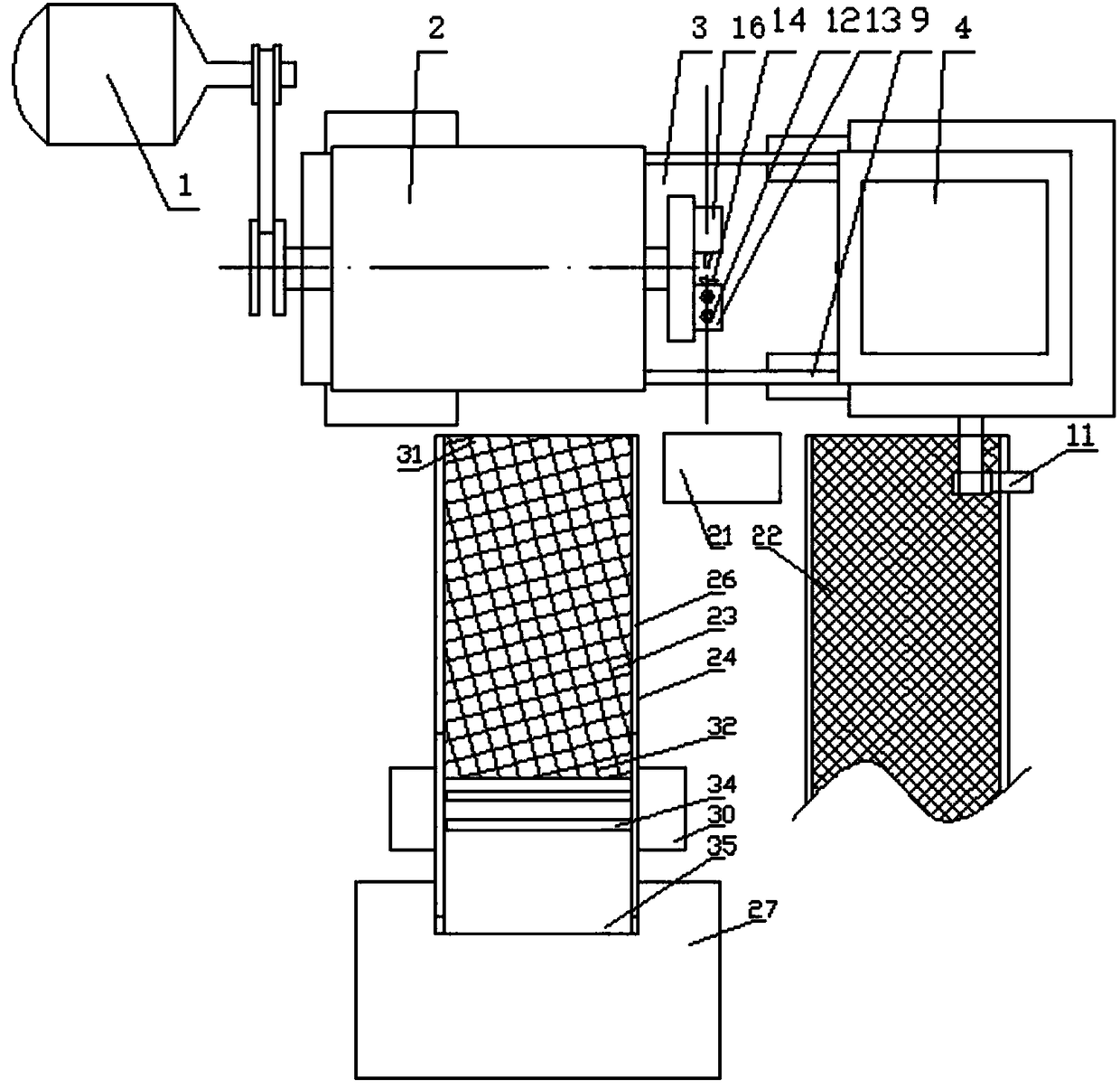
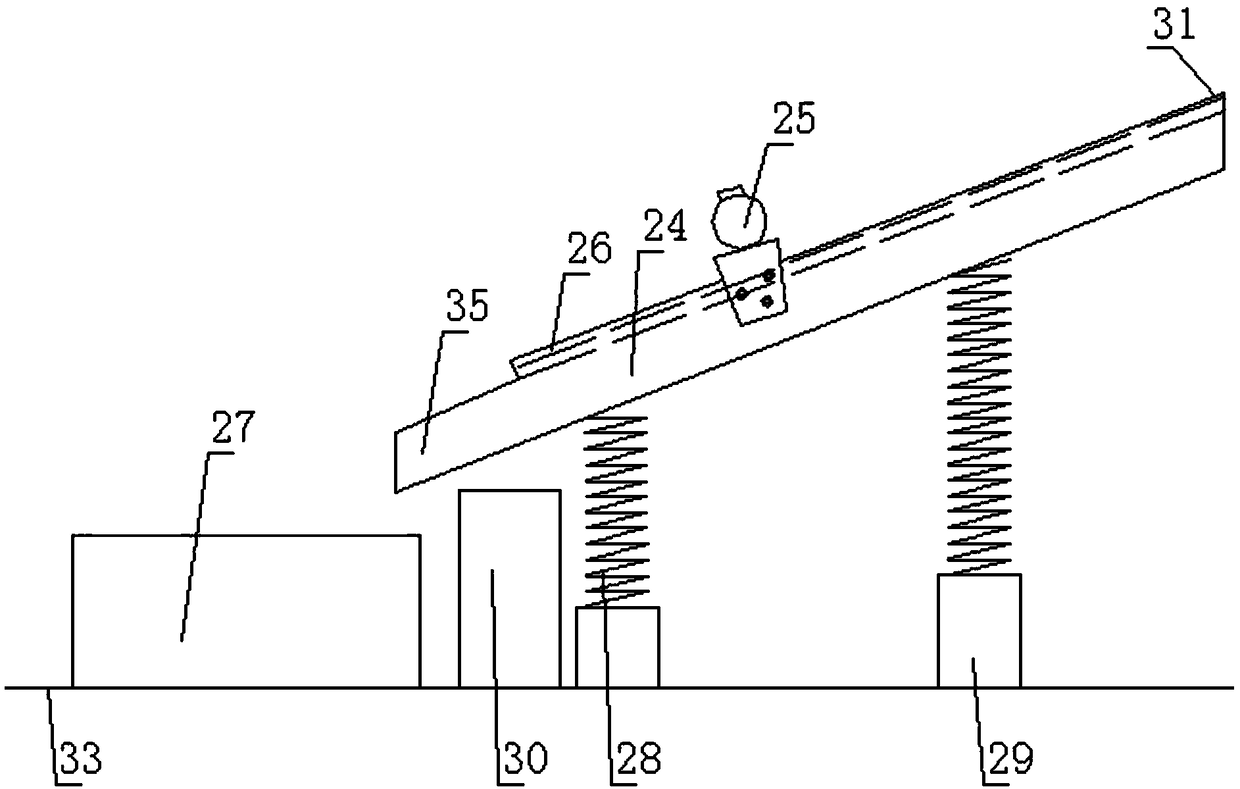
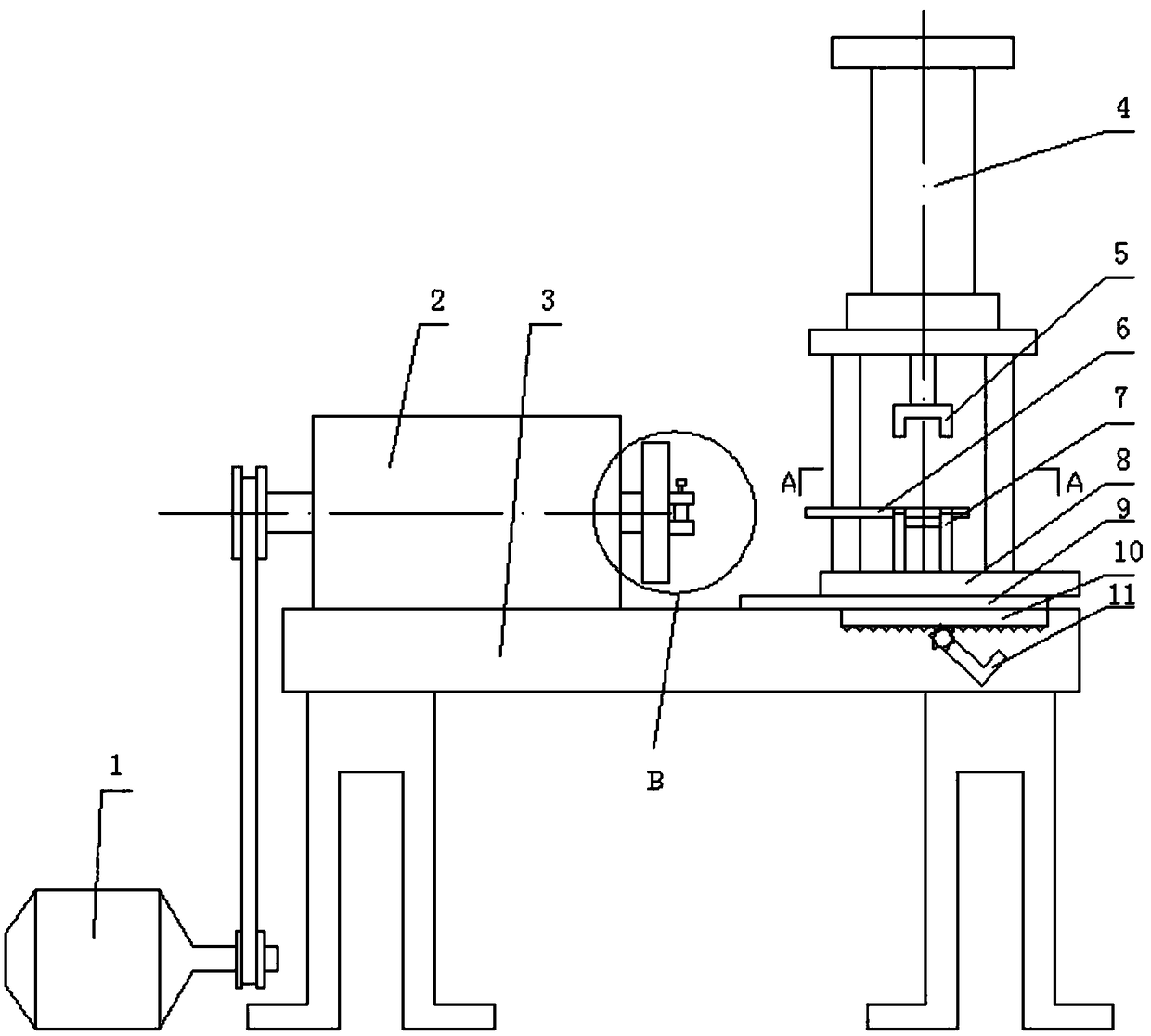
[0033] A valve stem guide fillet system, such as figure 1 and figure 2As shown, the system includes a rounding device, a valve input device 22, a vibration device and a collection device, the rounding device is arranged along the horizontal direction, and the operator's operating station is arranged on one longitudinal side of the rounding device 21. Valve input equipment, vibration equipment and collection equipment are arranged at intervals on both sides of the operating station horiz...


PUM


Abstract

The present invention relates to a fillet system for a valve stem. The system comprising a fillet device, valve input equipment, vibration equipment and collecting equipment, wherein the fillet deviceis arranged in a horizontal direction; ab operation station for an operator is arranged on the longitudinal side of the fillet device; the valve input equipment, the vibration equipment and the collection equipment are arranged on two horizontal sides of the operation station at intervals; one end of the valve input equipment and that of the vibration equipment are both arranged close to the fillet device; the valve input equipment can deliver the semi-finished valve stem to be rounded to the operator at the operation station; and the output end of the valve input equipment and the input endof the vibration equipment are both arranged close to the operation station. The system is scientific and reasonable in design and simple in structure, thereby greatly reducing the labor intensity ofthe operator and improving work efficiency.

Description

technical field [0001] The invention belongs to the technical field of valve production, and relates to production equipment for valves, in particular to a guide fillet system for valve stems. Background technique [0002] The valve is a control component in the fluid delivery system, which has functions such as cut-off, adjustment, flow diversion, reverse flow prevention, pressure stabilization, flow diversion or overflow pressure relief. Valves used in fluid control systems range from the simplest cut-off valves to various valves used in extremely complex automatic control systems, with a wide variety of varieties and specifications. Valves can be used to control the flow of various types of fluids such as air, water, steam, various corrosive media, mud, oil, liquid metal and radioactive media. There are various types of industrial valves, which are widely used in chemical industry, food, water, electricity and other industries, and mainly play the role of flow regulation...

Claims


Application Information

Patent Timeline
IPC IPC(8): B23C3/12B23Q3/08B23Q3/12B23Q7/00B23Q11/00
CPCB23C3/12B23Q3/062B23Q3/08B23Q3/12B23Q7/00B23Q11/0042B23Q2703/04
Inventor 郑家滨王鹏刘浩刘运洪陈洪才叶军国
Owner 天津市莱斯特阀门有限公司
Features
  • Generate Ideas
  • Intellectual Property
  • Life Sciences
  • Materials
  • Tech Scout
  • Unparalleled Data Quality
  • Higher Quality Content
  • 60% Fewer Hallucinations
Learn More