Front mixed abrasive jet generating device

A technology of abrasive jet and generating device, applied in abrasive feeding device, used abrasive processing device, abrasive and other directions, can solve problems such as insufficient uniformity, potential safety hazards, sedimentation, etc., to enhance turbulent flow intensity and safety Enhanced, evenly mixed effect

Active Publication Date: 2018-10-02
WUHAN UNIV
View PDF14 Cites 15 Cited by
  • Summary
  • Abstract
  • Description
  • Claims
  • Application Information

AI Technical Summary

Problems solved by technology

[0003] However, because the mixing of the abrasive and water in the pre-mixed abrasive jet is carried out in the abrasive tank, the uniformity of the mixing of the abrasive and the water is not enough, and the concentration of the abrasive in the high-pressure abrasive jet is difficult to control
In addition, the abrasive particles in the abr

Method used


Image

  • Front mixed abrasive jet generating device
  • Front mixed abrasive jet generating device

Examples


Embodiment 1

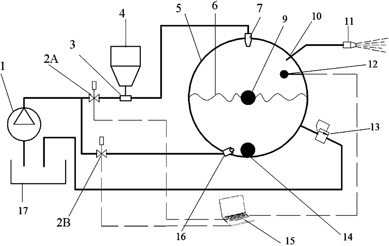
[0022] Example 1, such as figure 1 As shown, a pre-mixed abrasive jet generating device is mainly composed of a high-pressure pump 1, a solenoid valve, a jet pump 3, an abrasive box 4, an abrasive tank 5, a high-pressure nozzle 7, a cutter 11, an abrasive concentration sensor 12, a vibrating ball 9, Stirring ball 14, overflow valve 13, self-oscillating pulse nozzle 16, control computer 15 and water tank 17;

[0023] The high-pressure pump 1, solenoid valve 2A, jet pump 3 and high-pressure nozzle 7 are connected through a high-pressure pipeline to form a first branch, the abrasive box 4 is connected to the low-pressure inlet of the jet pump 3, and the high-pressure nozzle 7 is fixed on the abrasive Pot 5 top, and point to the center of abrasive pot 5;

[0024] The abrasive pot 5 is spherical and hollow inside. A vibrating ball 9 is fixed by two springs 6 at the center of the sphere in the cavity. The jet stream ejected from the high-pressure nozzle 7 just hits the vibrating ba...

Embodiment 2

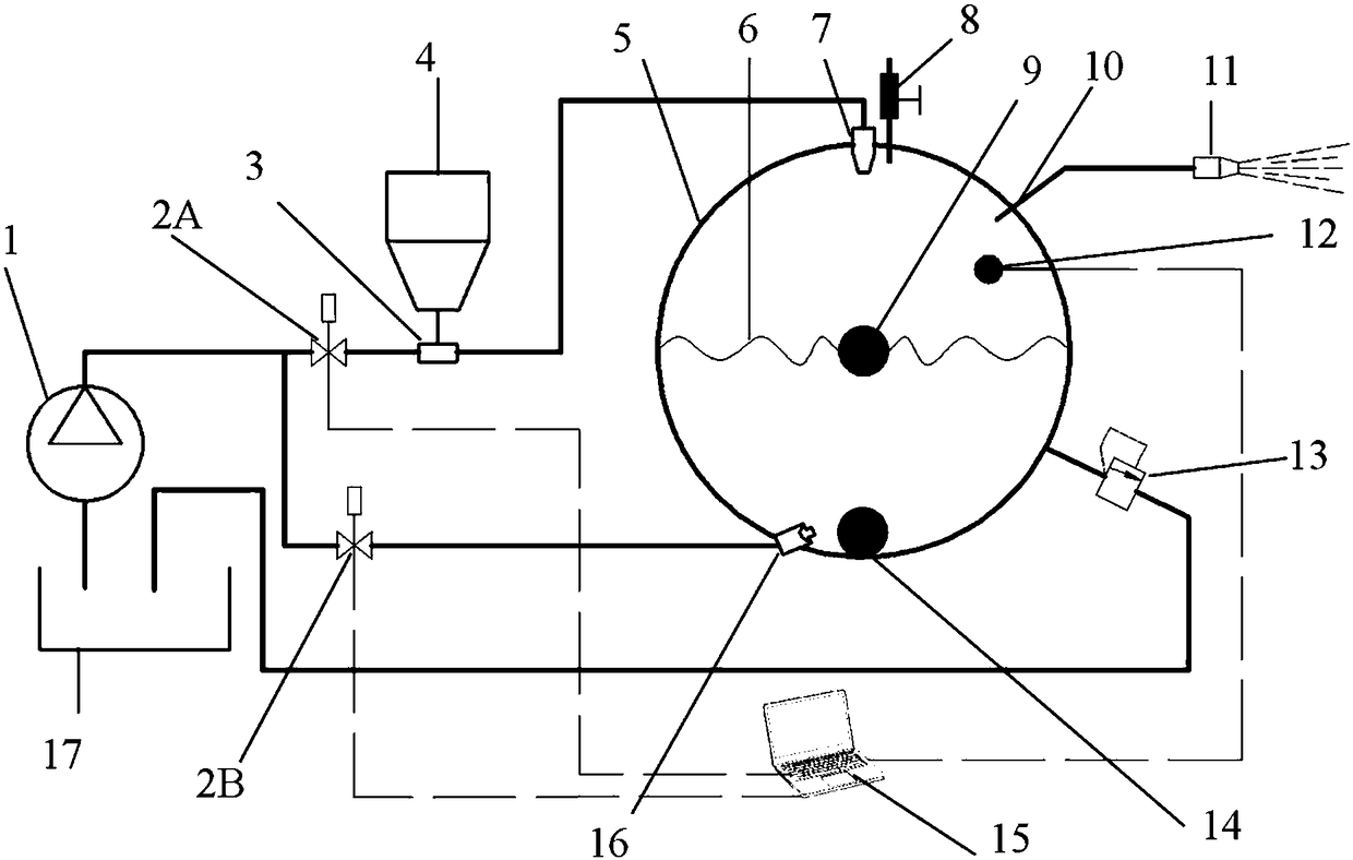
[0029] Example 2, such as figure 2 As shown, the structure of this embodiment is the same as that of Embodiment 1, the difference is that an exhaust valve 8 is set at the top high point in the abrasive tank 5, and the working mode and principle of this embodiment are basically the same as that of Embodiment 1, the difference is that in Open the high-pressure nozzle 7 to fill the abrasive tank 5, open the exhaust valve 8 to exhaust, when the abrasive tank 5 is completely full, close the exhaust valve, and open the outlet and cutter to cut after the abrasive tank 5 reaches the set pressure. The embodiment uses the exhaust valve 8 to allow the abrasive tank 5 to be fully operated, which can effectively prevent the gas from entering the cutter through the outlet, causing water hammer to damage the outlet pipeline and the cutter.

[0030] As another preferred embodiment, the abrasive tank 5 is a pressure vessel, on which there are safety accessories for the pressure vessel, includ...


PUM


Abstract

The invention discloses a front mixed abrasive jet generating device. The front mixed abrasive jet generating device is composed of a high-pressure pump, electromagnetic valves, a jet pump, an abrasive box, an abrasive tank, a high-pressure nozzle, a cutter, an abrasive concentration sensor, a vibrating ball. a stirring ball, an overflow valve, a self-vibration pulse nozzle and a control computer;the high-pressure nozzle is fixed at the top end of the abrasive tank and points to the center of the abrasive tank; the vibrating ball is fixed at the center of the spherical abrasive tank through two springs, and the stirring ball with the larger water density is static at the bottom of the cavity; the self-vibration pulse nozzle is fixed on one side of the bottom of the abrasive tank and points to the stirring ball; an outlet is formed in the upper part of the abrasive tank and is connected with the cutter through a high-pressure pipeline, and the abrasive concentration sensor is arrangednearby the outlet; and the two electromagnetic valves and the abrasive concentration sensor are connected with a control computer through a data line. Compared with the prior art, the front mixed abrasive jet generating device has the advantage that the uniformity degree of mixing of abrasive and water can be remarkably increased, the concentration of the abrasive can be accurately controlled, andthe potential safety hazard caused by the settlement of the abrasive can be avoided.

Description

technical field [0001] The invention belongs to the technical field of abrasive water jet cutting, and relates to a pre-mixed water jet cutting device, in particular to a pre-mixed abrasive jet generating device. Background technique [0002] Abrasive water jet cutting technology has become a new technology that has developed rapidly in recent years because of its unparalleled cold cutting advantages and non-selectivity to cutting materials. According to the different mixing methods of abrasive and water, it can be divided into pre-mixing abrasive jet and post-mixing abrasive jet. Compared with the post-mixed abrasive jet, the abrasive and high-pressure water in the front-mixed abrasive jet are evenly mixed, the abrasive particles are accelerated sufficiently, and the energy transmission efficiency is high. Under the same working pressure, the cutting ability of the front mixed abrasive jet can reach 4 to 10 times that of the rear mixed abrasive jet. Therefore, the pre-mix...

Claims


Application Information

Patent Timeline
IPC IPC(8): B24C7/00B24C9/00B24C1/04
CPCB24C1/045B24C7/0007B24C7/0015B24C9/00
Inventor 李登康勇王晓亮王晓川汪祖安范奇
Owner WUHAN UNIV
Why Eureka
Try Eureka