
A special engraving device for fully automatic ceramic surface processing

A ceramic surface, fully automatic technology, applied in the direction of ceramic molding machines, manufacturing tools, etc., can solve the problems of high labor intensity, large engraving error rate, long processing time, etc., to achieve reduced labor intensity, fast processing speed, and high processing efficiency Effect

Active Publication Date: 2020-02-14
安徽省亚欧陶瓷有限责任公司
View PDF5 Cites 0 Cited by
  • Summary
  • Abstract
  • Description
  • Claims
  • Application Information

AI Technical Summary

Problems solved by technology

All the existing ceramics on the market basically have engraving on the surface. The existing engraving process is basically processed manually by experienced engravers. This manual engraving processing method has long processing time, high labor intensity, and engraving error rate. Large size, low engraving efficiency and other problems
[0003] The invention patent of the patent application publication number CN105619577A discloses a special engraving equipment for fully automatic ceramic surface processing. Compared with the prior art, it drives the manipulator through the up and down movement of the No. 1 hydraulic cylinder and the circular transmission mode of the four transmission branches. The fully automatic engraving operation on the outer wall of the ceramic body solves the problems of long processing time, high labor intensity, high engraving error rate, and low engraving efficiency in the existing manual engraving processing methods, and also realizes fully automatic engraving on the ceramic surface. Engraving function, and has the advantages of short processing time, high engraving precision, no need for manual processing and high engraving efficiency. However, in the actual use process, the friction between the engraving knife and the ceramic body will generate a lot of dust. This technical solution does not control the dust. Processing will cause dust to pollute the working environment, and manual secondary cleaning is required in the later stage. At the same time, it can be further optimized in terms of improving processing efficiency.

Method used


Image

  • A special engraving device for fully automatic ceramic surface processing
  • A special engraving device for fully automatic ceramic surface processing
  • A special engraving device for fully automatic ceramic surface processing

Examples


Embodiment 1

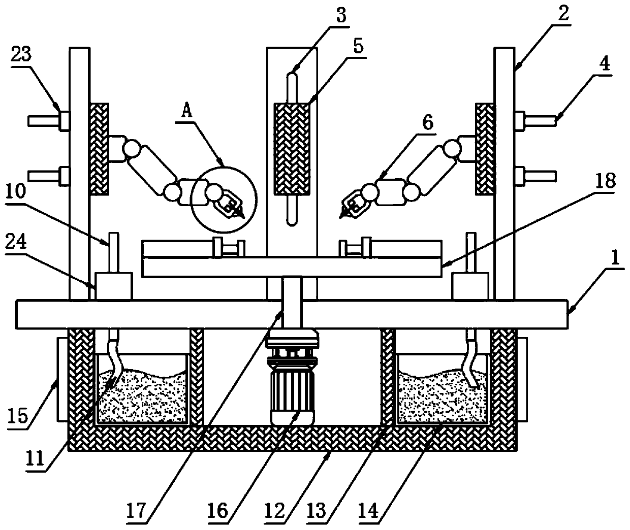
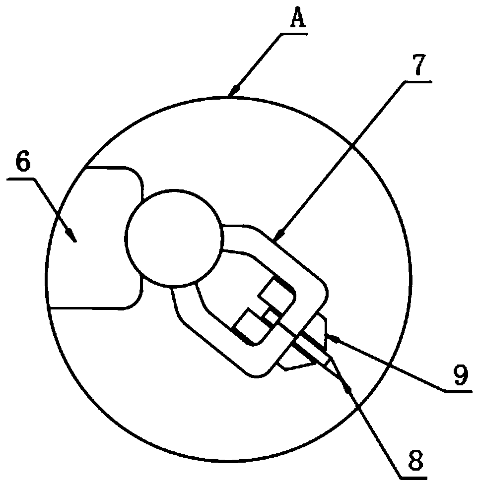
[0023] The present invention provides such Figure 1-3 A special engraving device for full-automatic ceramic surface processing as shown includes a workbench 1, a plurality of mounting plates 2 are fixed on the top of the workbench 1, and a mechanical arm base 5 is provided on the front side of the mounting plate 2, so that One side of the mechanical arm base 5 is fixed with a mechanical arm 6, the end of the mechanical arm 6 is provided with an electric clamp 7, and the electric clamp 7 is provided with a dust discharge pipeline 9, and the dust discharge pipeline 9 is connected with the electric clamp. 7 is fixedly connected, the electric clamp 7 is clamped with a carving knife 8, and the carving knife 8 is arranged between the dust discharge pipes 9, and the workbench 1 is penetrated with a delivery hard pipe 10, and the delivery hard pipe 10 is provided with a blower 24, the bottom end of the delivery hard pipe 10 is provided with a first hose 11, the bottom of the workbenc...

Embodiment 2

[0026] Further, in the above-mentioned embodiment 1, the mounting plate 2 is provided with a chute 3, and the other side of the mechanical arm base 5 is fixed with a screw 4, and the screw 4 is arranged inside the chute 3, so that A fastening nut 23 is threadedly connected to the outside of the screw rod 4, so as to adjust the height of the mechanical arm base 5.

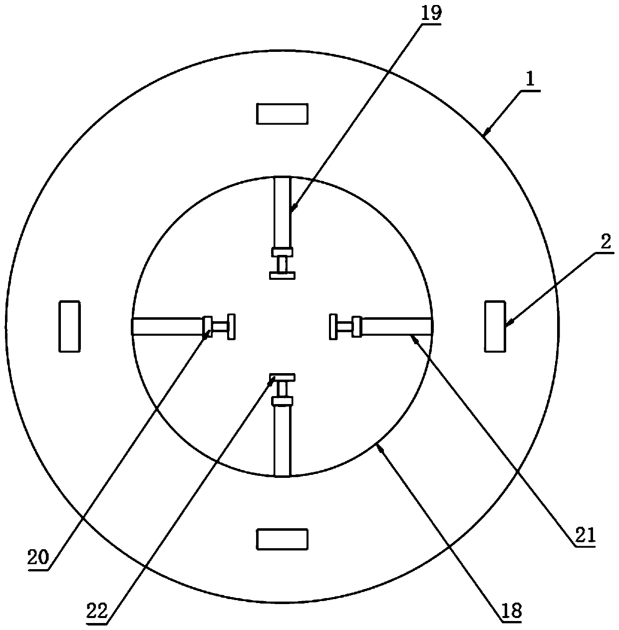
[0027] The carrying base 12 is provided with a motor 16 inside, the motor 16 is arranged inside the annular sealing plate 13, and the top of the motor 16 is provided with a rotating rod 17, and the rotating rod 17 runs through the bottom of the workbench 1 and extends to the workbench 1 At the top, a rotating table 18 is fixed on the top of the rotating rod 17 , and a limit mechanism 19 is fixed on the top of the rotating table 18 .

[0028] The limit mechanism 19 includes a limit installation plate 20, which is fixed on the top of the rotary table 18, the limit installation plate 20 is fixedly provided with a cylin...


PUM


Abstract

The invention discloses a special carving device for full-automatic ceramic surface machining. The device comprises a worktable; multiple mounting plates are fixedly arranged at the top of the worktable; mechanical arm bases are arranged on the front sides of the mounting plates; mechanical arms are fixedly arranged on one side surfaces of the mechanical arm bases; electric fixtures are arranged at the end parts of the mechanical arms; dust removing pipes are inserted in the electric fixtures, and are fixedly connected with the electric fixtures; carving cutters are clamped on the electric fixtures; the dust removing pipes are arranged on the two sides of the caving cutters; a conveying hard pipe is inserted in the worktable; and an air blower is arranged on the conveying hard pipe. Dust is effectively collected and treated to prevent direct scattering in the working environment, so that the labor intensity of operators is effectively reduced; meanwhile, the multiple mechanical arms can be used for synchronously machining the surfaces of ceramic blanks, so that the machining speed is higher, and the machining efficiency is higher compared with the prior art; and the device is suitable for industrial ceramic production.

Description

technical field [0001] The invention relates to the technical field of ceramic processing equipment, in particular to a special engraving device for fully automatic ceramic surface processing. Background technique [0002] Engraving is an indispensable process in the process of ceramic processing. The ceramic engraving process refers to using bamboo or iron tools to carve various depths and areas on the surface of the dried or semi-dried ceramic body. The main purpose of engraving is to engrave different patterns and colors with a carving knife to increase the shadow effect on the outer wall of the ceramic, thus highlighting the three-dimensionality of the engraving itself. All the existing ceramics on the market basically have engraving on the surface. The existing engraving process is basically processed manually by experienced engravers. This manual engraving processing method has long processing time, high labor intensity, and engraving error rate. Large size, low engra...

Claims


Application Information

Patent Timeline
Patent Type & Authority Patents(China)
IPC IPC(8): B28B11/00
CPCB28B11/001
Inventor 郑辉
Owner 安徽省亚欧陶瓷有限责任公司
Learn More