
Fourdrinier section dewatering mechanism

A technology of machine wire section and net paper, which is applied in the field of dehydration mechanism of fourdrinier paper machine wire section, which can solve the problems of long dehydration line and difficult precise control of pulp turbulence, and achieve the effect of increasing output and improving dehydration ability

Pending Publication Date: 2018-10-02
玖龙纸业(重庆)有限公司
View PDF17 Cites 0 Cited by
  • Summary
  • Abstract
  • Description
  • Claims
  • Application Information

AI Technical Summary

Problems solved by technology

The existing technology is to directly wipe the bottom of the forming wire through the wiper board. This method of dehydration requires a long dehydration line, and it is difficult to accurately control the turbulence of the pulp.

Method used


Image

  • Fourdrinier section dewatering mechanism
  • Fourdrinier section dewatering mechanism
  • Fourdrinier section dewatering mechanism

Examples


Embodiment 1

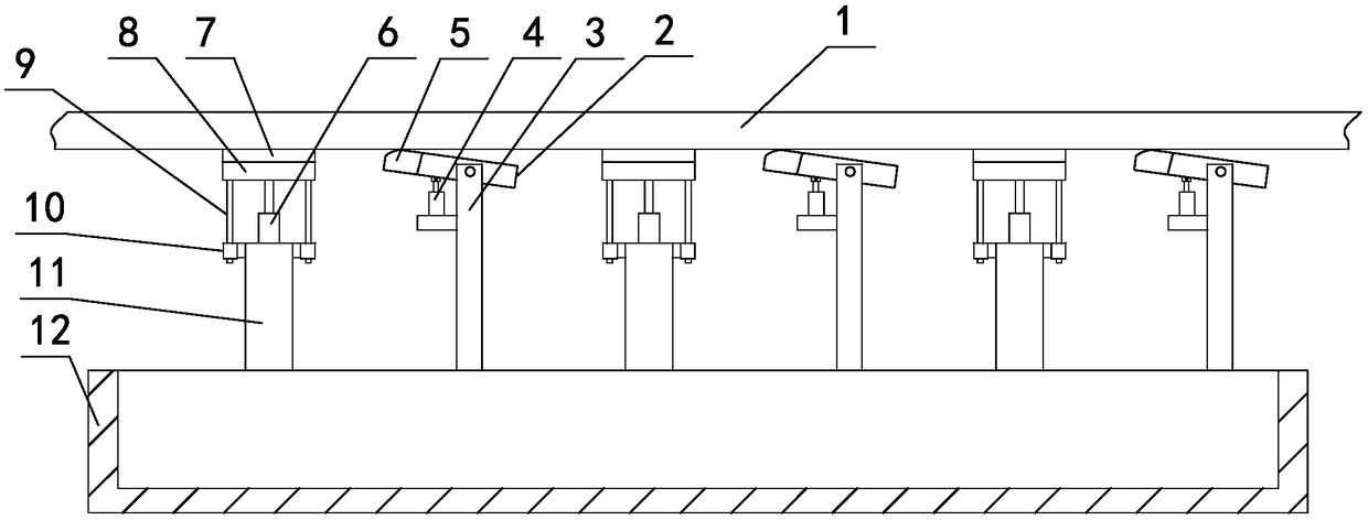
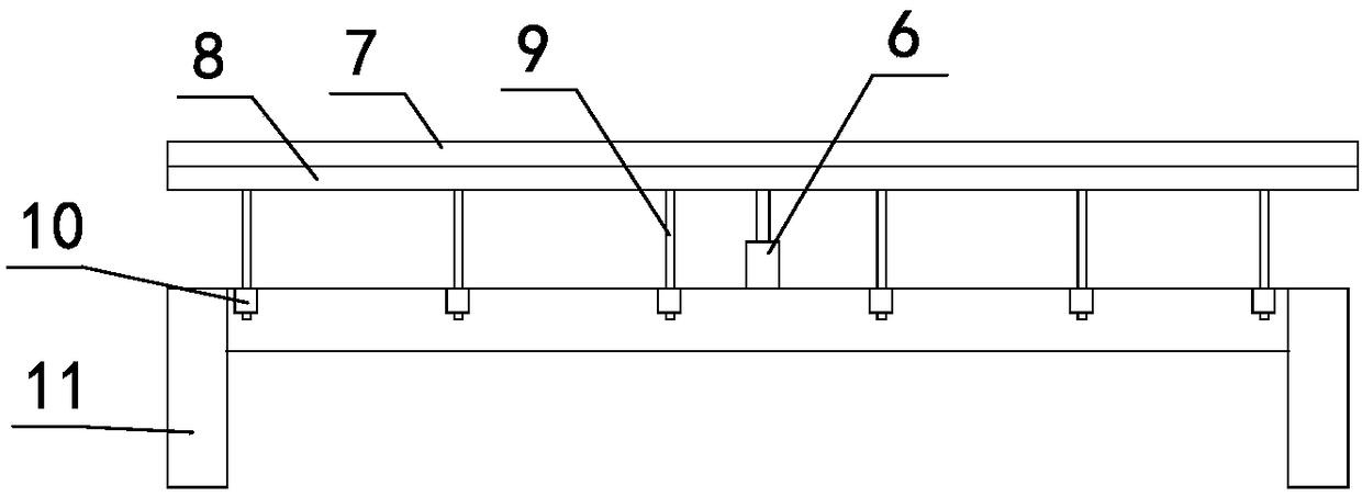
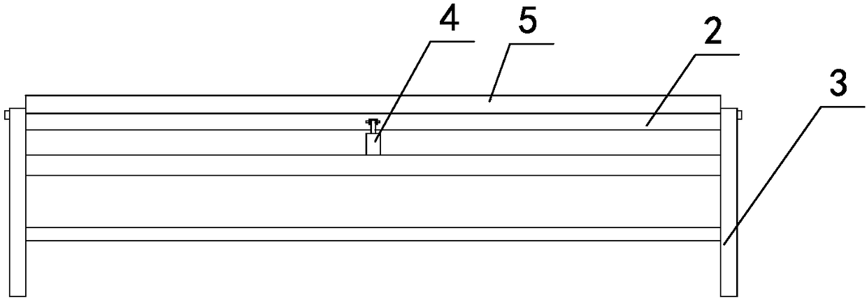
[0027] Such as figure 1 As shown, the dehydration mechanism of the fourdrinier paper machine wire section includes several groups of horizontally spaced brackets arranged horizontally, and each group of brackets includes a first bracket 3 and a second bracket 11 arranged horizontally spaced horizontally. The second bracket 11 is located at the first The left side of the bracket 3; the first bracket 3 is equipped with a rotating shaft arranged horizontally before and after, the first mounting plate 2 is installed on the rotating shaft, and corresponding to the first mounting plate 2 is provided with a handle for adjusting the rotation angle of the first mounting plate 2 Angle adjustment mechanism, a first wiper blade 5 for wiping is installed on the first mounting plate 2; a second mounting plate 8 is horizontally arranged on the front and back above the second bracket 11, and a second mounting plate 8 for wiping is installed on the second mounting plate 8. The second wiper bla...

Embodiment 2

[0039] Changes are made on the basis of Example 1, such as Figure 4 As shown, the angle adjustment mechanism and the lifting mechanism in Embodiment 1 are replaced, and the specific scheme is as follows:

[0040]Described angle adjusting mechanism comprises the rotating casing 13 that is vertically arranged on the left and right sides of first bracket 3, and threaded rod 14 is worn in the rotating casing 13, and the upper end of threaded rod 14 is hinged with first mounting plate 2, and threaded rod 14 and the rotating sleeve 13 are threaded, and the lower end of the rotating sleeve 13 is connected with a power mechanism for the rotating sleeve 13 to rotate positively and negatively; the power mechanism in this section of technology adopts a motor, and a servo motor and other motors can also be used. When in use, the rotating sleeve 13 is driven to rotate by using the positive and negative rotation of the motor. At this time, under the thread cooperation between the rotating ...


PUM


Abstract

The invention relates to a fourdrinier section dewatering mechanism and belongs to the technical field of fourdrinier section dewatering. The fourdrinier section dewatering mechanism comprises a plurality of sets of supports; each set of supports include a first support and a second support, the second support is positioned on the left of the first support, a rotary shaft is mounted on the first support, a first mounting plate is mounted on the rotary shaft, an angle adjusting mechanism is arranged in correspondence with the first mounting plate, a first water scraper for scraping water is mounted on the first mounting plate, second mounting plates are horizontally arranged in the front and rear of the top of the second support, a second scraper for scraping water is mounted on each secondmounting plate, and a lifting mechanism is arranged between the second mounting plates and the second support. The principle used herein refers to: adjusting forming uniformity by changing a dewatering fit mode between scrapers and a forming web; since the dewatering fit mode is changed to adjust dewatering turbulence of formed pulp, dewatering capacity is improved, the yield is increased, and basis is laid for improving paper uniformity.

Description

technical field [0001] The invention relates to a fourdrinier paper machine wire dehydration mechanism, which belongs to the technical field of fourdrinier paper machine wire dehydration. Background technique [0002] In the wire forming process in the papermaking process, dehydration of the slurry on the forming wire is a very important link, and the degree of dehydration determines the evenness of the subsequent paper. At present, the commonly used forming fabric is made of polyester and polyurethane, which has certain stability and abrasion resistance. The forming fabric is used in the wire part of the paper machine to support the fiber and remove the free water in the pulp. It is the core component of papermaking to make the forming of the paper sheet and complete the transfer of the paper sheet. The existing technology is to directly wipe water on the bottom of the forming wire through the wiper blade. This method of dehydration requires a long dehydration line, and it...

Claims


Application Information

Patent Timeline
Patent Type & Authority Applications(China)
IPC IPC(8): D21F1/66
CPCD21F1/66
Inventor 李雄蒋科
Owner 玖龙纸业(重庆)有限公司
Learn More