Motor

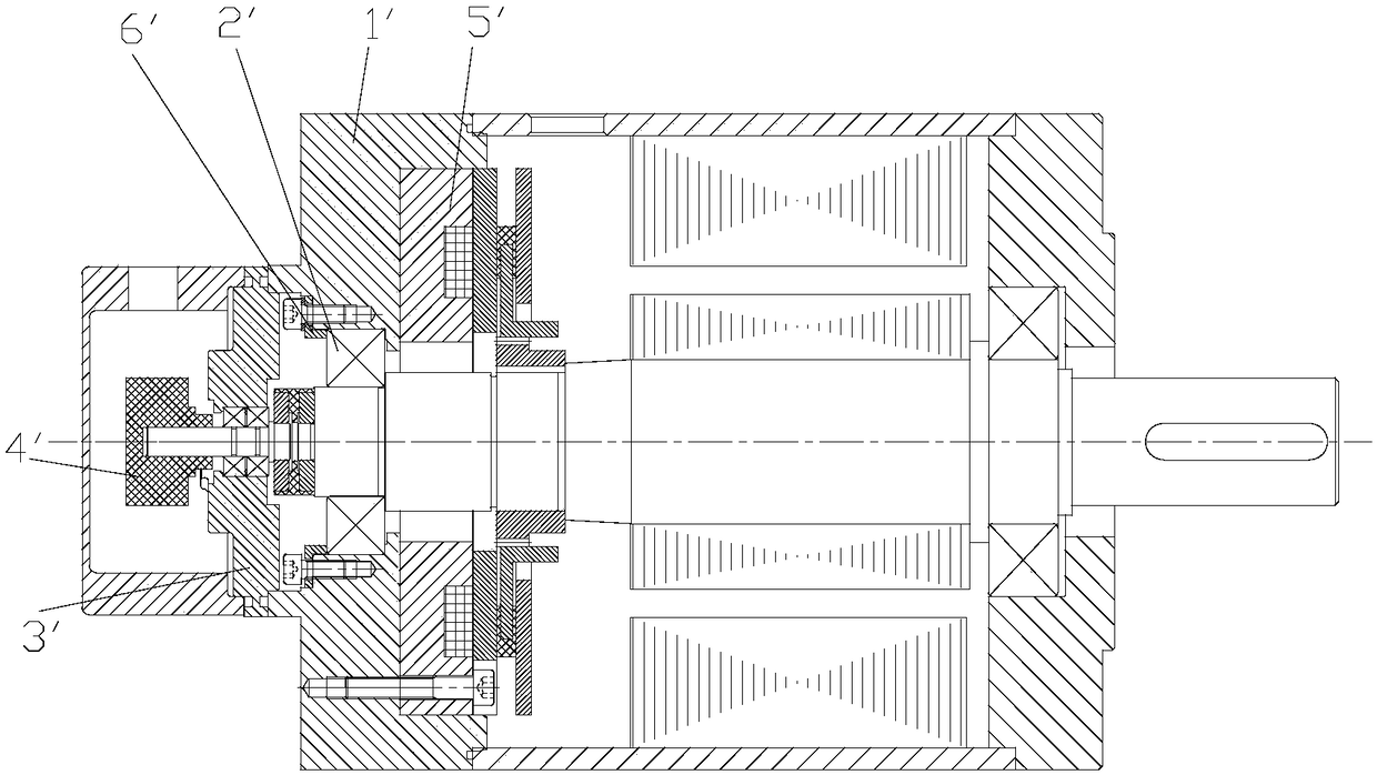
A casing and brake technology, applied in electrical components, electromechanical devices, electric components, etc., can solve the problems of reducing the heat dissipation efficiency of the brake 5', reducing the heat dissipation area of ​​the brake 5', and the encoder 4' being easily damaged, etc. The effect of shortening the length of the motor, simple structure, and avoiding excessive temperature rise

Pending Publication Date: 2018-10-02
GREE ELECTRIC APPLIANCES INC +1
View PDF0 Cites 4 Cited by
  • Summary
  • Abstract
  • Description
  • Claims
  • Application Information

AI Technical Summary

Problems solved by technology

[0003] like figure 1 As shown, the traditional motor structure supports the rear bearing 2' through the rear end cover 1', and the two are in the form of an interference fit. Due to the different materials, the thermal expansion of the rear end cover 1' is greater than that of the rear bearing 2'. The amount is large, resulting in insufficient interference between the rear end cover 1' and the rear bearing 2', which affects the reliability of the bearing.
And this solution needs to increase the rear bearing cover plate 6' to axially locate the rear bearing 2', and the installation is relatively troublesome
[0004] In addition, due to the limitation of the structure of the rear end cover 1', the distance between the shaft end cover 3' and the brake winding is relatively close, and the brake winding is the main heat-generating part of the brake 5', resulting in excessive temperature of the encoder 4', and the encoder 4' prone to damage
[0005] In addition, the rear end cover 1' is set outside the brake 5', which reduces the heat dissipation area of ​​the brake 5'. The heat dissipation of the brake 5' needs to be carried out through the rear end cover 1'. Because the materials of the two are different, it will cause heat transfer. resistance, reduce the heat dissipation efficiency of the brake 5', and cause the temperature rise of the motor to be too high

Method used


Image

  • Motor
  • Motor
  • Motor

Examples


Embodiment Construction

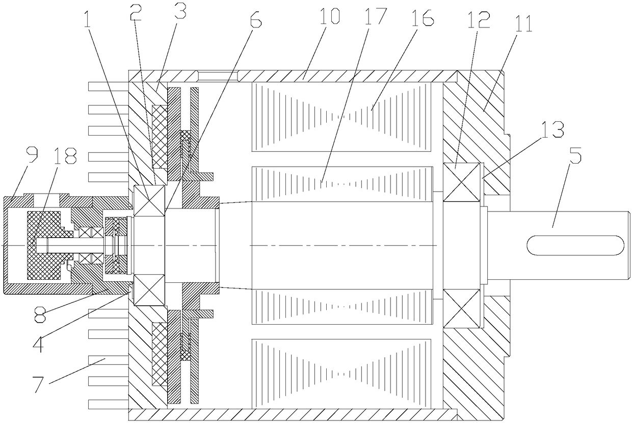
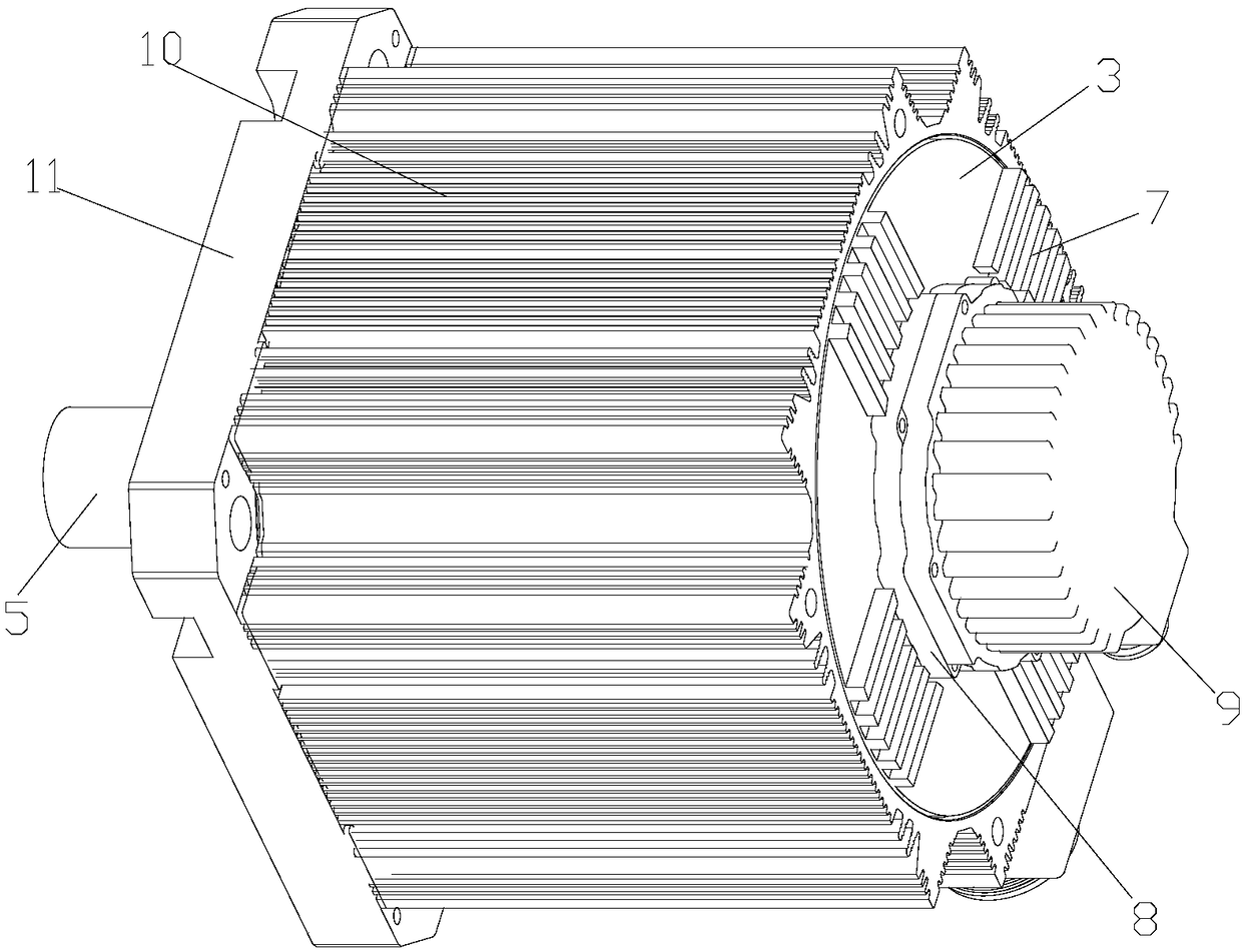
[0029] see in conjunction Figure 2 to Figure 9 As shown, according to the embodiment of the present invention, the motor includes a rear bearing 1 and a brake. The brake is provided with a first bearing chamber 2 , and the rear bearing 1 is limitedly installed in the first bearing chamber 2 .

[0030] The motor is provided with a first bearing chamber 2 on the brake, and then the rear bearing 1 is installed in the first bearing chamber 2, so there is no need to set a separate rear end cover for installing the rear bearing 1, the rear end cover structure can be omitted, and the Reduce the cost, shorten the length of the motor, facilitate the miniaturization of the motor, make the structure of the motor simpler, and improve the power density of the motor; since the first bearing chamber 2 is directly arranged on the brake, the rear end cover structure is omitted, so the brake can be used Direct heat exchange with the outside air reduces the heat transfer resistance of the brake...


PUM


Abstract

The invention provides a motor. The motor comprises a rear bearing (1) and a brake, wherein a first bearing chamber (2) is arranged on the brake, and the rear bearing (1) is arranged in the first bearing chamber (2) in a limitation way. According to the motor, the cooling efficiency of the motor brake can be improved, and excessively high temperature rise of the motor is prevented.

Description

technical field [0001] The invention belongs to the technical field of motors, and in particular relates to a motor. Background technique [0002] The motor is an electromagnetic device that realizes the conversion and transmission of electric energy according to the principle of electromagnetic induction. Its main function is to generate driving torque, and it is the power source of electrical appliances and various mechanical equipment. [0003] like figure 1 As shown, the traditional motor structure supports the rear bearing 2' through the rear end cover 1', and the two are in the form of an interference fit. Due to the different materials, the thermal expansion of the rear end cover 1' is greater than that of the rear bearing 2'. The amount is large, resulting in insufficient interference between the rear end cover 1' and the rear bearing 2', which affects the reliability of the bearing. And this scheme needs to increase rear bearing cover plate 6 ' to carry out axial ...

Claims


Application Information

Patent Timeline
Patent Type & Authority Applications(China)
IPC IPC(8): H02K7/10H02K5/16
CPCH02K7/10H02K5/163
Inventor 钟成堡马艳娇陈飞龙谢芳杨文德
Owner GREE ELECTRIC APPLIANCES INC
Why Eureka
Try Eureka