Push force-adjustable flow one-way control device

A one-way control and adjustable technology, applied in the direction of electromechanical devices, cooling/ventilation devices, electrical components, etc., can solve the problems of low back pressure, small heat dissipation area, high power density of drive motor, etc., and achieve simple structure and reliable opening thrust. The effect of adjusting and improving the adjustment accuracy

Inactive Publication Date: 2018-10-02
MAANSHAN JULI SCI & TECH
View PDF0 Cites 2 Cited by
  • Summary
  • Abstract
  • Description
  • Claims
  • Application Information

AI Technical Summary

Problems solved by technology

However, due to the high power density of the drive motor, the heat is more serious, and air cooling or water cooling is often used. Due to the small size of the drive motor, air cooling is limited by the small heat dissipation area, resulting in poor heat dissipation, and water cooling is used. The current method is the main measure. In the water cooling system, a one-way valve will be installed in the pipeline as a directional control device. However, since the opening pressure of the one-way valve is constant and cannot be adjusted, it cannot meet the requirements of various working conditions. For example, when the water pump starts , the back pressure of a certain section of the pipeline needs to be low during the start-up phase, and the back pressure is constant during normal operation

Method used


Image

  • Push force-adjustable flow one-way control device
  • Push force-adjustable flow one-way control device
  • Push force-adjustable flow one-way control device

Examples


Embodiment Construction

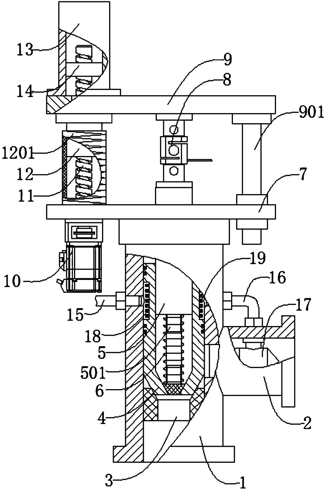
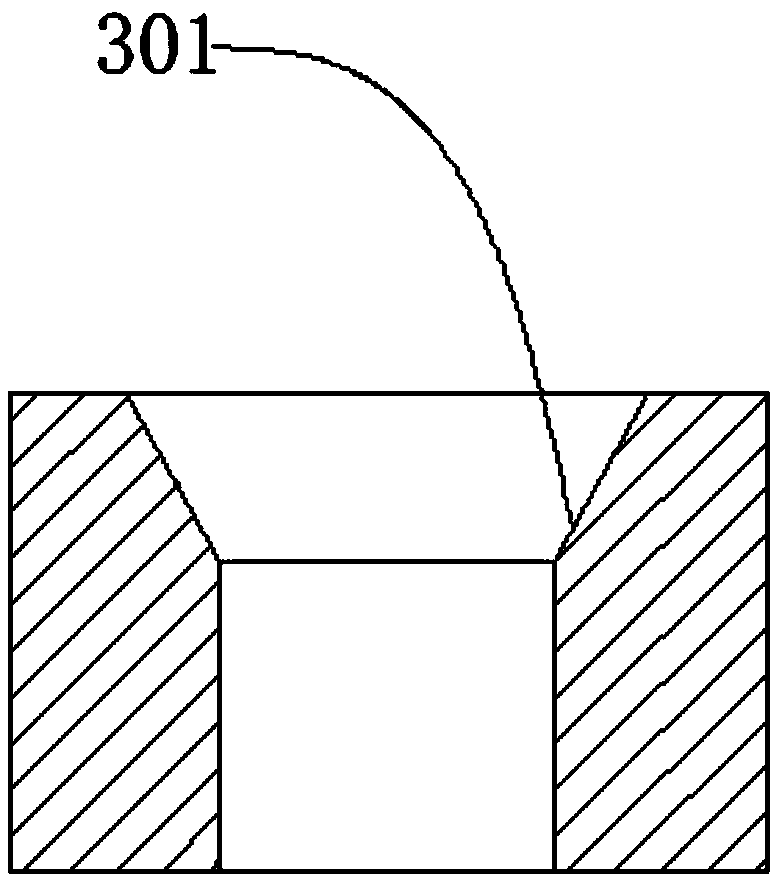
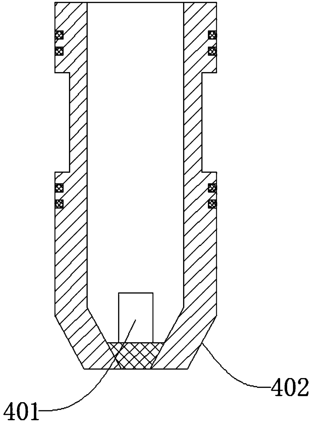
[0019] Such as figure 1 , figure 2 , image 3 , Figure 4As shown, a thrust adjustable flow one-way control device includes a main pipe 1, a branch pipe 2, a throttle seat 3, a sealing head 4, a push rod 5, a spring 6, an end plate 7, a pull pressure sensor 8, a top plate 9, and a servo Motor 10, lead screw 11, feed nut 12, protective cover 13, swivel seat 14, water inlet pipe 15, water outlet pipe 16, heat spreader 17, cooling ring groove 18, cooling fin 19, the branch pipe 2 is located in the main pipe 1 on the right side, the branch pipe 2 is integrally connected with the main pipe 1, the throttle seat 3 is located at the inner lower end of the main pipe 1, the throttle seat 3 is threadedly connected with the main pipe 1, and the sealing head 4 is located at the throttle The upper end of the seat 3 is located inside the main pipe 1. The sealing head 4 can slide up and down along the main pipe 1. The push rod 5 penetrates the main pipe 1 and extends into the sealing head...


PUM


Abstract

The invention discloses a push force-adjustable flow one-way control device. The push force-adjustable flow one-way control device comprises a main pipe, a branch pipe, a throttling seat, a sealing head, a push rod, a spring, an end plate, a pull pressure sensor, a top plate, a servo motor, a lead screw, a feeding nut, a protection cover, a rotation seat, a water inlet pipe, a water outlet pipe, athermal spreader, a cooling annular groove and cooling fins. The device is simple in structure, the opening push force of the sealing head is adjustable, the device is applicable to different workingcondition demands, the sealing head and the main pipe can be cooled, the service lifetime is prolonged, and the reliability is improved; and meanwhile, a hot medium passing through the main pipe canbe cooled, and the comprehensive utilization rate of a cold medium is effectively improved.

Description

technical field [0001] The invention relates to a mechanical device, in particular to a thrust adjustable flow one-way control device. Background technique [0002] Drive motors are one of the three core components of new energy vehicles. Compared with traditional industrial motors, drive motors for new energy vehicles have higher technical requirements. Like ordinary motors, new energy drive motors are mainly composed of three parts: stator, rotor, and mechanical structure. However, due to the high power density of the driving motor, the heat generation is more serious, and air cooling or water cooling is often used. Due to the small size of the driving motor, air cooling is limited by the small heat dissipation area, resulting in poor heat dissipation, and water cooling is used. The current method is the main measure. In the water cooling system, a one-way valve will be installed in the pipeline as a directional control device. However, since the opening pressure of the o...

Claims


Application Information

Patent Timeline
IPC IPC(8): H02K9/19
CPCH02K9/19
Inventor 王照柱
Owner MAANSHAN JULI SCI & TECH
Why Eureka
Try Eureka