Zero-pressure connector

A zero-pressure, zero-compression technology, applied to needles, devices introduced into the body, etc., can solve the problems of poor patient recovery and high infection risk.

Pending Publication Date: 2018-10-09
郑州迪奥医学技术有限公司
View PDF0 Cites 0 Cited by
  • Summary
  • Abstract
  • Description
  • Claims
  • Application Information

AI Technical Summary

Problems solved by technology

[0003] At the same time, with the improvement of living standards, the number of people seeking medical treatment is increasing day by day, especially when an epidemic breaks out. In general, nurses will take out more connectors for spare use to save patients' time; during this process, ordinary connectors are exposed to the surroundings when they are not connected to liquid. In the environment, there is a greater risk of infection, which is not good for the patient's recovery

Method used


Image

  • Zero-pressure connector
  • Zero-pressure connector
  • Zero-pressure connector

Examples


Embodiment 1

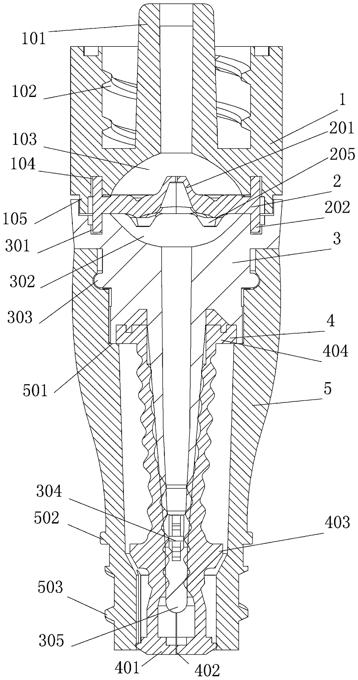
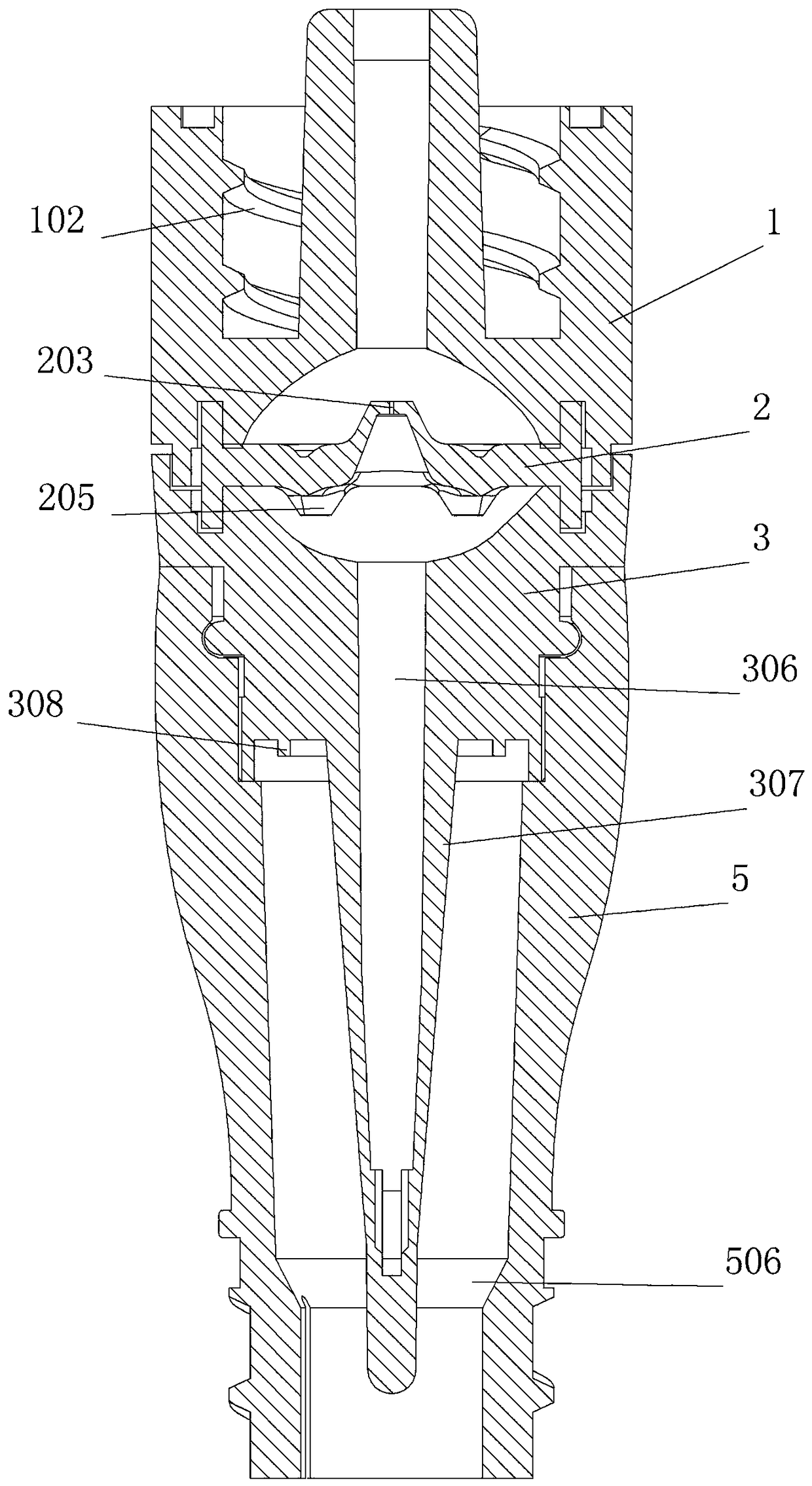
[0031] Embodiment one: see Figure 1-8 , a zero-pressure joint in the figure, which is mainly composed of an upper shell, a zero-pressure sheet, a drainage tube, a sealing sleeve, and an outer shell. Its characteristics are:

[0032] The upper shell is a cylinder, and the center has a joint protruding from the upper surface of the upper shell. The joint is a hollow cylinder, and its lower part is connected with the shell to divide the inner space of the upper shell into upper and lower parts. The upper part is surrounded by Internal thread, the middle part is the cylinder, this structure is convenient to connect with the upper joint which is a common joint; the lower part of the joint port has an upper hemispherical cavity, the outer side of the upper hemispherical cavity wall has an upper fixing groove, and the outer side of the upper fixing groove is the upper shell wall , There are protruding fixing ribs on the lower surface of the upper housing wall near the upper fixing g...

Embodiment 2

[0041] Embodiment two, according to the zero-pressure joint of embodiment one, its use method is:

[0042] ①. Connect the upper joint with the internal thread in the upper housing;

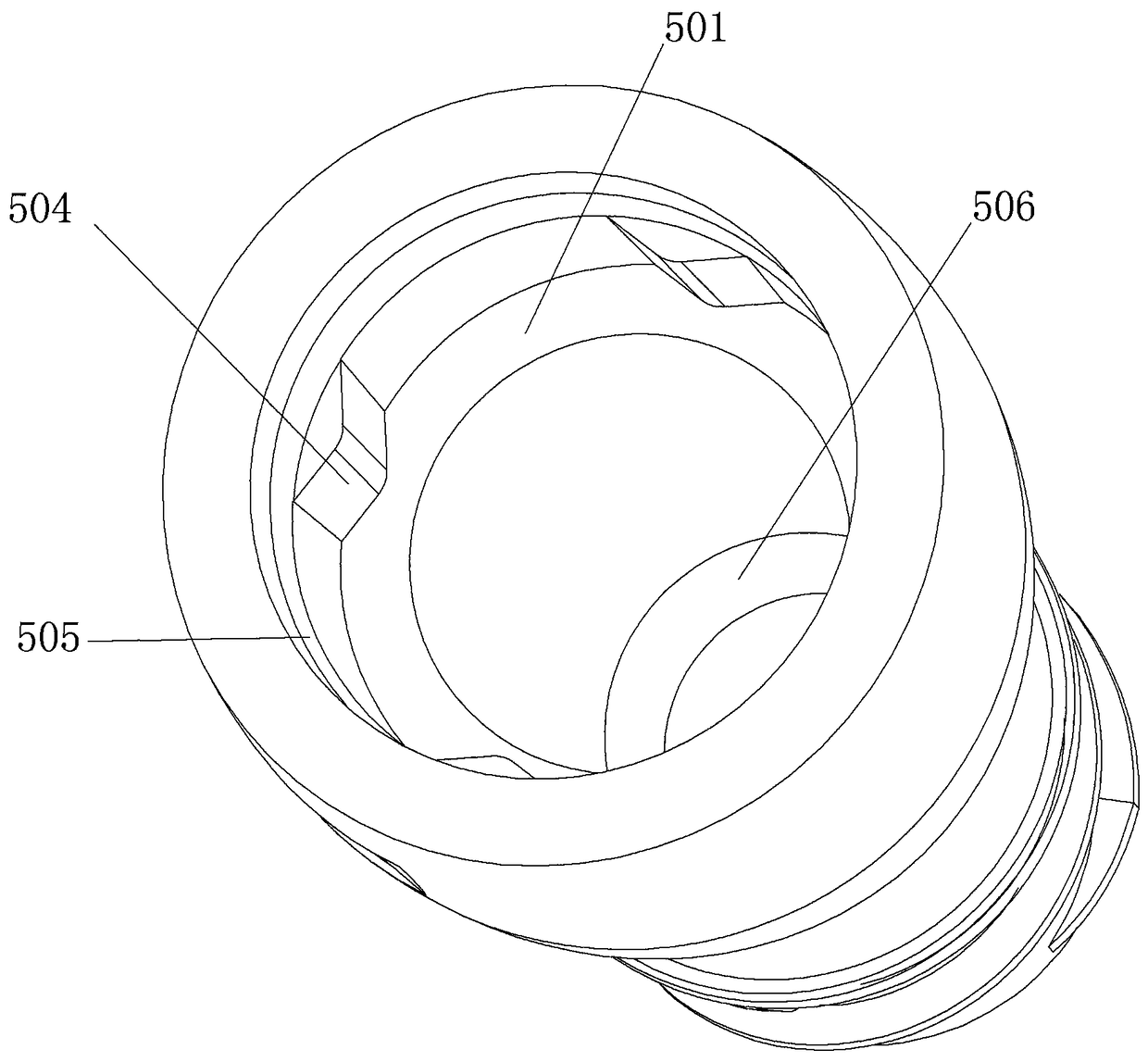
[0043] ②. Align the ribs in the middle of the lower joint with the sealing disc of the sealing sleeve, and forcefully push the sealing disc into the casing. At this time, the lower end of the drainage tube pushes the sealing disc through the gap in the middle, and the ribs continue to move up, so that The sealing plate is located above the drainage port, so that the interior of the drainage tube communicates with the interior of the lower joint; the lower joint is connected to the lower end of the shell through external threads.


PUM


Abstract

The invention discloses a zero-pressure connector. The zero-pressure connector is mainly composed of an upper shell, a zero-pressure sheet, a drainage pipe, a sealed casing pipe and a shell; an innerthread is arranged at the upper portion of the upper shell, and an upper hemispherical cavity is formed in the lower side in the upper shell; a lower hemispherical cavity opposite to the drainage pipeis formed in the upper portion of the drainage pipe, and the zero-pressure sheet is installed in the middle; the sealed casing pipe sleeves a conical pipe at the lower portion of the drainage pipe, the drainage pipe is welded to the shell, and the sealed casing pipe is extruded and fixed through gaps between the drainage pipe and the shell; an outer thread is arranged at the lower side of the shell. By means of the zero-pressure connector, an unanticipated blood return phenomenon caused when pressure of the human body and pressure of pipelines are different during infusion or blood drawing bya positive-pressure or negative-pressure connector is effectively avoided; when the connector is exposed, the sealed casing pipe can still protect the pipelines against infection, and the zero-pressure connector has high safety; duckbill valves are arranged on the zero-pressure sheet, and due to the effect of the duckbill valves, the zero-pressure function of the connector is maintained; meanwhile, since the two-way duckbill valves are designed on the zero-pressure sheet, the using range of the connector is wider.

Description

technical field [0001] The invention relates to medical supplies, in particular to a zero-pressure joint. Background technique [0002] At present, there are two main types of disposable sterile needle-free infusion connectors on the market, one is a positive pressure connector, and the other is a negative pressure connector. The positive pressure connector has a positive pressure effect, and a positive pressure will be generated when the infusion is completed. The function of preventing blood return, but the market price is relatively expensive. In ordinary infusion therapy, people usually choose a relatively cheap negative pressure connector, but the negative pressure connector has no positive pressure effect, and blood return will occur when the infusion is completed. Once the blood returns, it will frighten the patient and cause the patient's worry and uneasiness, and it will cause the infusion hose to be unable to continue the infusion due to bubble embolism. Therefore...

Claims


Application Information

Patent Timeline
IPC IPC(8): A61M5/158
CPCA61M5/158
Inventor 荆文普邢正伟司阳光梁承君
Owner 郑州迪奥医学技术有限公司
Why Eureka
Try Eureka