Testing method and combined testing device for puncture resistance capabilities of battery diaphragm

A test method and technology for battery separators, applied in measuring devices, instruments, scientific instruments, etc., can solve the problems of ignoring the influence of the puncture resistance of the separator and not being able to accurately evaluate the puncture resistance of the separator, and achieve comprehensive puncture resistance. Easy to operate, good detection repeatability

Active Publication Date: 2018-10-09
SOUNDON NEW ENERGY TECH CO LTD
View PDF11 Cites 10 Cited by
  • Summary
  • Abstract
  • Description
  • Claims
  • Application Information

AI Technical Summary

Problems solved by technology

The characterization of the puncture resistance of the diaphragm in the prior art basically uses the ASTMF1306-90 film puncture strength standard test method to test the puncture resistance of the diaphragm. The test method is to test the puncture resistance of the diaphragm with a diameter of 3.2mm. Press vertically into the diaphragm fixed on the clamping device. The pressure when the diaphragm is pierced is recorded as the puncture resistance of the diaphragm. The diameter of the puncture indenter used in this test method is obviously larger than that of lithium dendrites in the battery, metal burrs on pole pieces or Hundreds of times of foreign matter particles, etc., and ignore the impact of battery process temperature or service temperature on the puncture resistance of the separator
It can be seen that this test method is to directly test the puncture resistance of the separator sample with a puncture indenter at room temperature. This test result is quite different from the actual situation, and it is not enough to accurately evaluate the actual puncture resistance of the separator in the battery.

Method used


Image

  • Testing method and combined testing device for puncture resistance capabilities of battery diaphragm
  • Testing method and combined testing device for puncture resistance capabilities of battery diaphragm

Examples


Embodiment 1

[0055] This example tests the high-temperature puncture strength of a polyethylene wet-process separator with a thickness of 16 μm, simulates the battery baking process, and tests the puncture strength of the separator during battery baking. The specific operation steps are as follows:

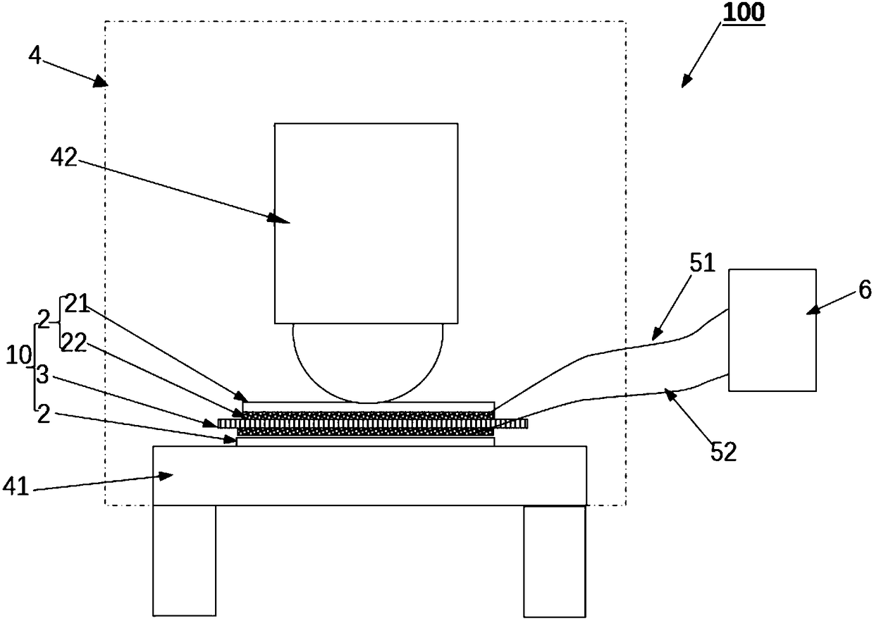
[0056] (1) Place a 120mm×120mm diaphragm sample on the upper and lower sides of 100mm×100mm on the copper foil with tiny burrs covering 30% to 40% of the surface area (the surface without burrs is coated with an insulating layer or pasted with insulating glue) ), the particle size of the burr on the copper foil is 50-80 μm, the height of the protrusion is 50-80 μm, and the surface of the burr faces the diaphragm sample. Bond the wires on the copper foil (bonded on the side without insulating layer or insulating film) and connect it to the insulation resistance tester, then place the copper foil and diaphragm together on the test platform in the high and low temperature universal testing machine...

Embodiment 2

[0059] This example tests the high-temperature puncture strength of a polyethylene wet-process separator with a thickness of 16 μm, simulates the battery baking process, and tests the puncture strength of the separator during battery baking. The specific operation steps are as follows:

[0060] (1) Place a 120mm×120mm diaphragm sample between two upper and lower dry sandpapers of 100mm×100mm, where the sand grains of the sand paper are tungsten carbide with a particle size of 40 μm, and bond the wires to the sand grain layers of the two dry sand papers Put it on and connect it with the insulation resistance tester, then put the two pieces of dry abrasive paper and the diaphragm sample together on the test platform in the high and low temperature universal testing machine, and place the insulation resistance tester outside the high and low temperature testing machine.

[0061] (2) The diaphragm sample is left to stand in the high and low temperature testing machine at 80°C for 3...

Embodiment 3

[0063]This example tests the low-temperature puncture strength of a polypropylene dry-process separator with a thickness of 40 μm, simulates the low-temperature use environment of the battery, and tests the puncture strength of the separator during low-temperature charging and discharging of the battery. The specific operation steps are as follows:

[0064] (1) Place a diaphragm sample of 120mm×100mm between two upper and lower dry sandpapers of 90mm×80mm, wherein the sand grains of the sand paper are titanium carbide with a particle size of 80 μm, and bond the wires on the sand grain surfaces of the two dry sand papers Connect with the insulation resistance tester, then put the two pieces of dry abrasive paper and the diaphragm sample together on the test platform in the high and low temperature universal testing machine, and the insulation resistance tester is placed outside the high and low temperature universal testing machine.

[0065] (2) The diaphragm sample is placed in...


PUM

PropertyMeasurementUnit
particle diameteraaaaaaaaaa
thicknessaaaaaaaaaa
thicknessaaaaaaaaaa

Abstract

The invention relates to a testing method for puncture resistance capabilities of battery diaphragm. The method includes that a diaphragm sample is put between two plate electrodes to form a test piece, the surface of at least one plate electrode is provided with burrs and comprises a plurality of hard conductive particles protruding out of the surface, the diaphragm sample is correspondingly placed on the burred surface in a contact mode, and the two plate electrodes are electrically connected to two sides of an insulated resistance tester; the test piece is put in an environment with changeable and controllable temperatures, and the pressure value of forward extrusion of the plate electrodes is increased through external force; when the insulated resistance tester detects short circuit of the plate electrodes of the test piece, the pressure value, used for representing the puncture resistance capability of the diaphragm sample, at the moment is recorded. Preferably, two dry abrasivepapers with hard conductive alloy particles on the surfaces are substituted for the two plate electrodes. The invention further relates to a combined testing device applied to tests of the puncture resistance capabilities of the battery diaphragm.

Description

technical field [0001] The invention relates to the technical field of batteries, in particular to a method for testing the puncture resistance of battery diaphragms. Background technique [0002] The separator is one of the key inner components in the structure of lithium batteries. The performance of the separator determines the interface structure and internal resistance of the battery, which directly affects the capacity, cycle and safety performance of the battery. A separator with excellent performance plays an important role in improving the overall performance of the battery. The popular description of the diaphragm is a layer of porous plastic film, which is a high value-added material with the highest technical barriers among lithium battery materials, accounting for about 20%-30% of the cost of lithium batteries. The diaphragm divides the electrolysis chamber into a cathode area and an anode area, which can allow lithium ions to migrate through and prevent the sh...

Claims


Application Information

Patent Timeline
Patent Type & Authority Applications(China)
IPC IPC(8): G01N3/00
CPCG01N3/00
Inventor 郭丽媛娄忠良
Owner SOUNDON NEW ENERGY TECH CO LTD
Why Eureka
Try Eureka