Liquid crystal display device and turning film for liquid crystal display device

一种液晶显示装置、转向膜的技术,应用在转向膜领域,能够解决颜色不均、亮度不均等问题,达到抑制亮度不均、抑制颜色不均的效果

Inactive Publication Date: 2018-10-09
KEIWA INCORPORATED
View PDF6 Cites 0 Cited by
  • Summary
  • Abstract
  • Description
  • Claims
  • Application Information

AI Technical Summary

Problems solved by technology

Therefore, if a film made of polyethylene terephthalate is used as an optical sheet of a liquid crystal display device, there is a possibility that the liquid crystal display device may have color unevenness and brightness unevenness due to polarization.

Method used


Image

  • Liquid crystal display device and turning film for liquid crystal display device
  • Liquid crystal display device and turning film for liquid crystal display device

Examples


no. 1 approach

[0038] [Liquid crystal display device]

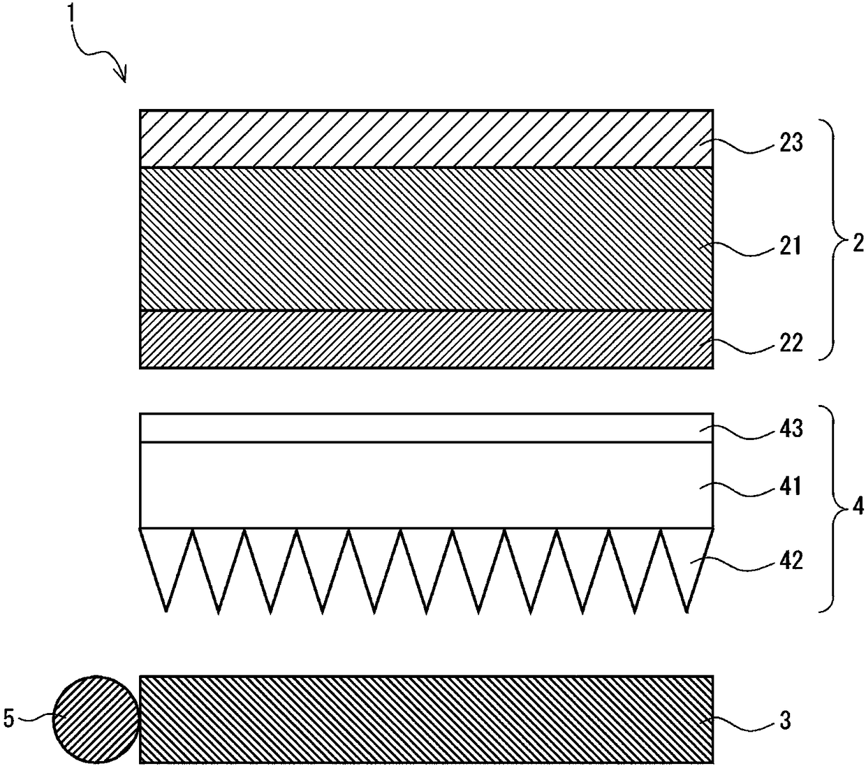
[0039] figure 1 The liquid crystal display device 1 comprises: a liquid crystal panel 2; a light guide plate (light guide film 3), which is overlapped on the back side of the liquid crystal panel 2, and guides the light incident from the end surface to the surface side; one or more LED light sources 5, It is arranged along the end surface of the light guide film 3 ; and the turning film 4 is overlapped between the liquid crystal panel 2 and the light guide film 3 . In addition, the light guide film 3 and the turning film 4 are transparent because light is to be transmitted therethrough. In addition, the liquid crystal display device 1 further includes a reflector that is superimposed on the back side of the light guide film 3 and reflects light incident from the front side toward the front side (not shown).

[0040]

[0041] The liquid crystal panel 2 has: a liquid crystal cell 21; a back side polarizing plate 22 disposed on the fac...

no. 2 approach

[0068] [Liquid crystal display device]

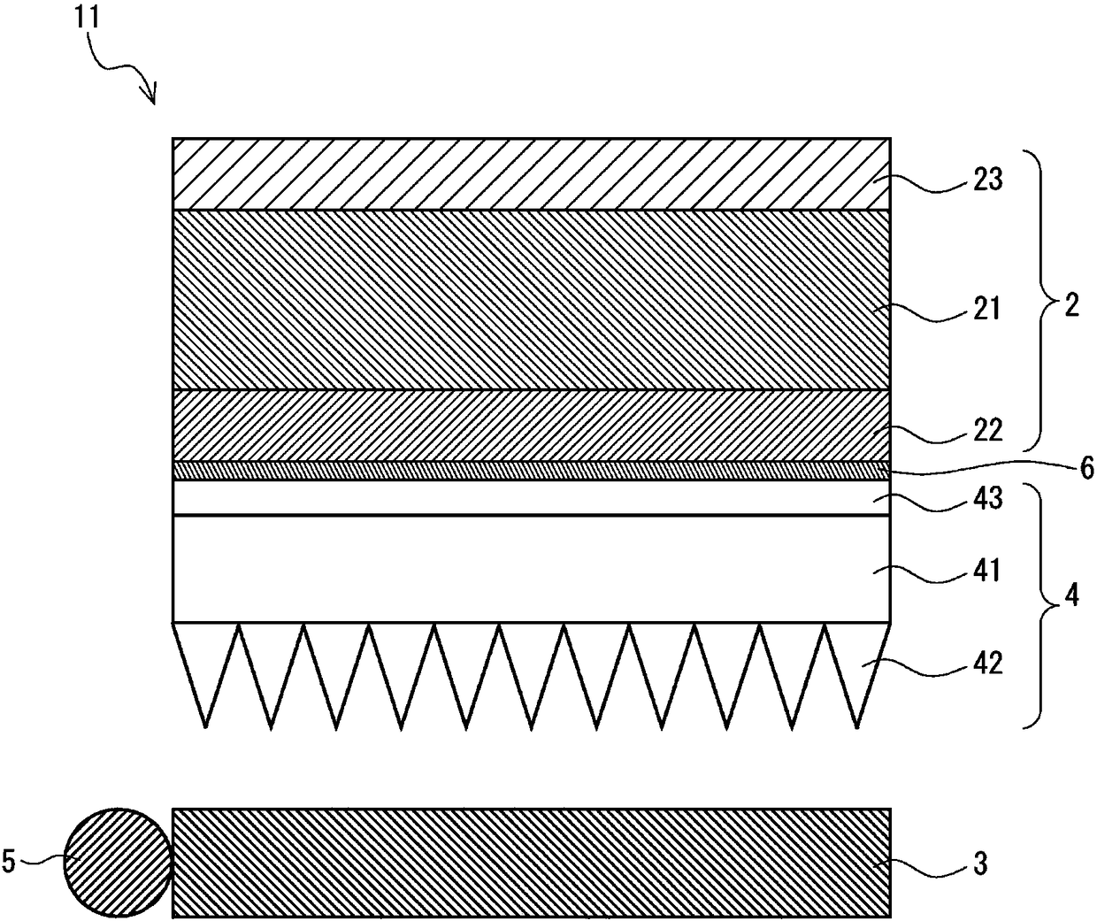
[0069] figure 2 The liquid crystal display device 11 comprises: a liquid crystal panel 2; a light guide plate (light guide film 3), which overlaps the back side of the liquid crystal panel 2, and guides the light incident from the end surface to the surface side; one or more LED light sources 5, It is arranged along the end surface of the light guide film 3 ; and the turning film 4 is overlapped between the liquid crystal panel 2 and the light guide film 3 . In addition, the liquid crystal display device 11 includes an adhesive layer arranged between the liquid crystal panel 2 and the turning film 4 . In addition to having the bonding layer 6, the liquid crystal display device 11 and figure 1 The configuration of the liquid crystal display device 1 is the same. Therefore, only the bonding layer 6 will be described below.

[0070] (junction layer)

[0071] The bonding layer 6 bonds the turning film 4 and other members laminated on ...


PUM

PropertyMeasurementUnit
refractive indexaaaaaaaaaa

Abstract

The present invention has an object to provide a liquid crystal display device and a turning film for use in a liquid crystal display device that are capable of inhibiting irregularities in color andluminance caused by polarization. The liquid crystal display device includes a liquid crystal panel; a light-guiding plate that is disposed on a back face side of the liquid crystal panel and is for guiding rays of light incident on an end face toward a front face side; an LED light source disposed along the end face of the light-guiding plate; and a turning film disposed between the liquid crystal panel and the light-guiding plate. The turning film includes: a substrate layer formed from a transparent resin; and a prism array disposed on a back face side of the substrate layer. A retardationvalue of the substrate layer is no less than 0 nm and no greater than 100 nm. In a planar view, a transmission axis of the back face side-polarizing plate of the liquid crystal panel is perpendicularto the end face of the light-guiding plate; the ridge lines in the prism array of the turning film are parallel to the end face of the light-guiding plate; and the transmission axis of the back face side-polarizing plate of the liquid crystal panel is perpendicular to the ridge lines in the prism array of the turning film.

Description

technical field [0001] The invention relates to a liquid crystal display device and a turning film for a liquid crystal display device. Background technique [0002] Conventionally, as an optical sheet for a liquid crystal display device, various optical sheets having different optical characteristics exist, and a structure obtained by combining these optical sheets is used for a backlight unit for a liquid crystal display device. For example, a polyester film obtained by providing a prism sheet layer on a base film made of polyester such as polyethylene terephthalate is disclosed as an optical film aimed at improving brightness (Patent Document 1). [0003] A film made of polyethylene terephthalate is generally produced by a biaxial stretching method. However, polyethylene terephthalate is a crystalline resin and has a large birefringence. Therefore, when polyethylene terephthalate is formed into a film by a biaxial stretching method, molecular orientation occurs dependin...

Claims


Application Information

Patent Timeline
Patent Type & Authority Applications(China)
IPC IPC(8): G02F1/1335G02F1/13363
CPCG02F1/1335G02F1/13363G02B1/045G02B6/0051G02B6/0053G02F1/133528G02F1/133507G02F1/133531G02F1/133603G02F1/133553G02B6/0056G02B6/0025
Inventor 辻孝弘
Owner KEIWA INCORPORATED
Why Eureka
Try Eureka