Locking type inertia switch

A technology of inertia switch and housing, applied in the field of inertia switch, can solve the problem of unreliable contact during closing time

A technology of inertia switch and housing, applied in the field of inertia switch, can solve the problem of unreliable contact during closing time

CN108630489AInactive Publication Date: 2018-10-09湖北三江航天红林探控有限公司

Image

  • Locking type inertia switch
  • Locking type inertia switch
  • Locking type inertia switch

Examples


Embodiment Construction

[0031] In order to make the object, technical solution and advantages of the present invention clearer, the present invention will be further described in detail below in conjunction with the accompanying drawings and embodiments. It should be understood that the specific embodiments described here are only used to explain the present invention, not to limit the present invention. In addition, the technical features involved in the various embodiments of the present invention described below can be combined with each other as long as they do not constitute a conflict with each other.

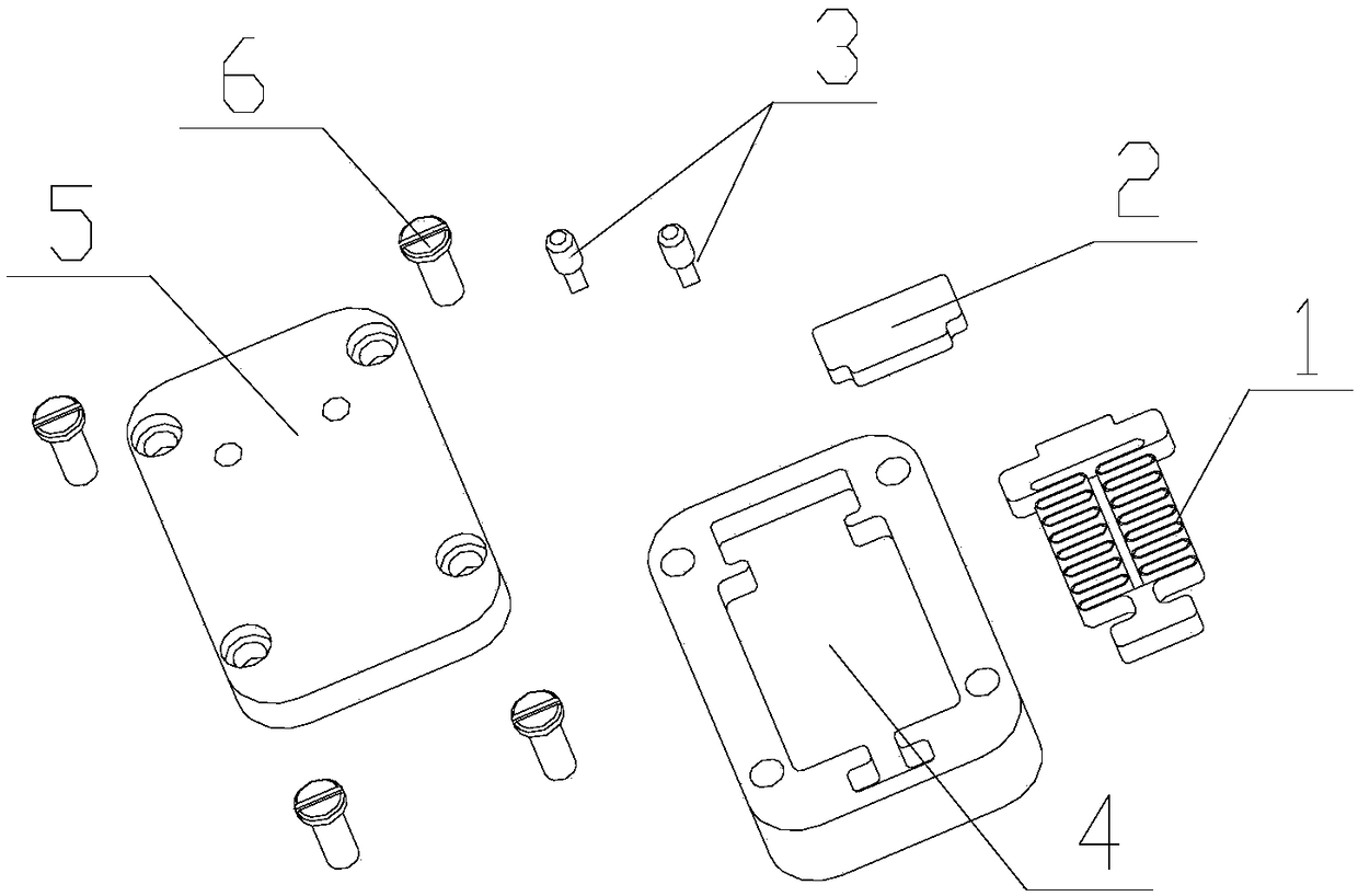
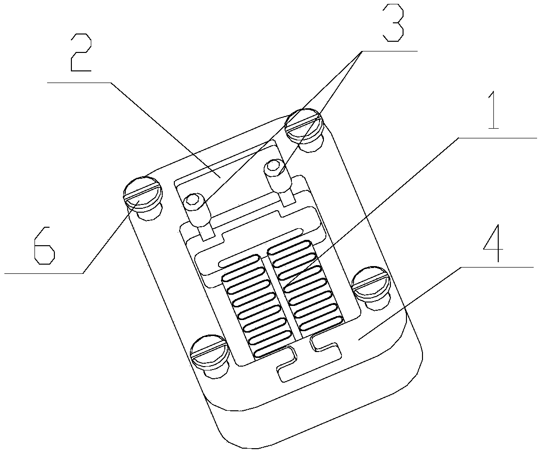
[0032] figure 1 It is an exploded view of a latching inertia switch according to an embodiment of the present invention, figure 2 It is a structural schematic diagram of the initial state after assembly of a latch type inertial switch according to an embodiment of the present invention. Such as figure 1 and figure 2 As shown, a latch type inertial switch includes a spring mass 1 , a magnet...


PUM


Abstract

The invention discloses a locking type inertia switch which comprises a magnet (2), a screw (6) a spring mass block (1), a conductive column (3), a shell (4) and a cover plate (5), wherein one end ofthe spring mass block (1) is fixedly connected with the shell (4), the other end of the spring mass block (1) keeps a certain distance from the shell (4), one end of the conductive column (3) is a cylinder and is fixedly arranged in a conductive column hole in the cover plate (5) in an interference fit mode (5), and the other end of the conductive column (3) is a rectangular sheet, the cover plate(5) is fixedly installed with the shell (4) through the screw (6) to realize locking in place. According to the locking type inertia switch, when the spring mass block senses overload, the spring mass block overcomes the force resistance of the spring under the action of inertia force and the suction force of the spring mass block and the magnet until the spring mass block is in contact with theconductive column, so that the on and off of the circuit are realized, and the in-place locking function is achieved.

Description

technical field [0001] The invention belongs to the technical field of inertial switches, and more specifically relates to a locking type inertial switch. Background technique [0002] Inertial switches have a wide range of applications in aerospace, automotive electronics, and ammunition. Micro-electromechanical (MEMS) inertial switch is an acceleration sensor manufactured by micro-machining technology. It uses inertial sensitive elements to convert the acceleration load into changes in the electrode gap, and then triggers the corresponding electrical signal through the contact state between the electrodes to realize the function of distinguishing acceleration signals. Due to the advantages of small size, light weight, low energy consumption, strong resistance to high overload, strong resistance to electromagnetic interference, and easy integration with digital circuits, MEMS inertial switches are widely used in demanding environments such as industrial vibration detection,...

Claims


Application Information

Patent Timeline
09 Oct 2018
Publication
CN108630489A
IPC
H01H35/14
CPC
H01H35/14
Inventors
李响; 邬学聪