
Battery temperature management system

A technology for managing system and battery temperature, applied to secondary batteries, battery/fuel cell control devices, circuits, etc., can solve problems such as accelerating internal chemical reactions, overcharging, battery safety hazards, etc., to improve utilization efficiency and use The effect of life and rapid heat transfer

Inactive Publication Date: 2018-10-09
HAIMA AUTOMOBILE CO LTD
View PDF4 Cites 5 Cited by
  • Summary
  • Abstract
  • Description
  • Claims
  • Application Information

AI Technical Summary

Problems solved by technology

[0004] Due to the strict temperature requirements of the battery, the allowable temperature range of the battery is roughly 5°C to 35°C. When the battery is cooled by natural water cooling, when the ambient temperature is too high, this method cannot reduce the temperature of the battery. In the suitable temperature range, the high temperature of the battery will accelerate the internal chemical reaction, damage the battery plate, easily lead to overcharging, and seriously affect the service life of the battery; when the ambient temperature is too low, because this method has no heating function, it cannot When the temperature of the battery rises to the appropriate working temperature range, the reaction resistance of the battery at low temperature increases greatly, the discharge capacity rapidly decays, and the internal pressure rises faster during charging, which poses hidden dangers to battery safety.

Method used


Image

  • Battery temperature management system
  • Battery temperature management system
  • Battery temperature management system

Examples


Embodiment 1

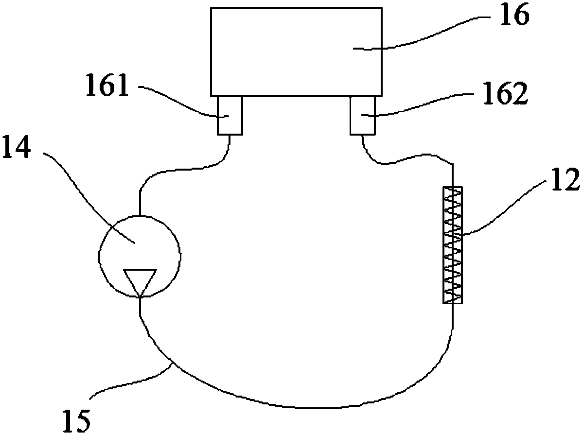
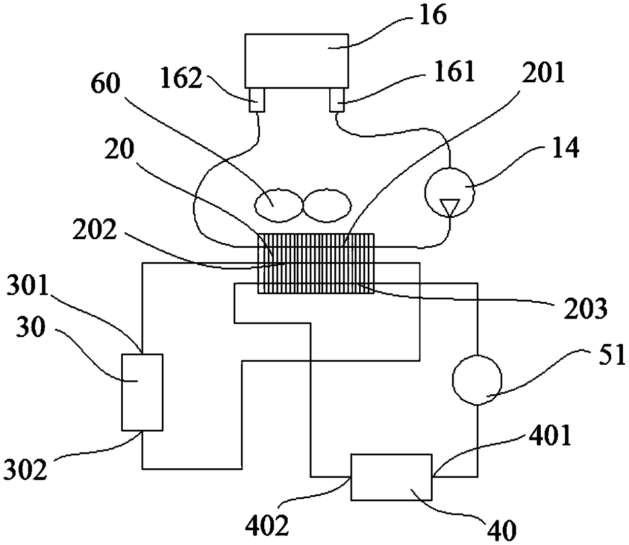
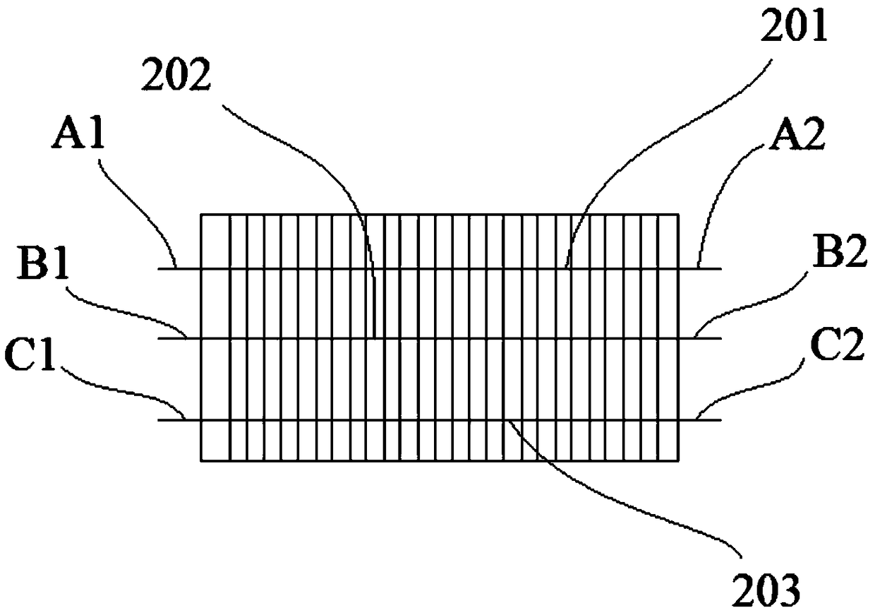
[0045] figure 2 It is a schematic diagram of the connection of the battery temperature management system of this embodiment, from figure 2 It can be seen from the figure that the water outlet 161 of the battery pack box 16 is connected with the first water pump 14, the heat exchange element 20 and the water inlet 162 of the battery pack box 16 in turn through the pipe body. Under the action of the first water pump 14, the internal The natural water can be circulated between the battery case 16 and the heat exchange element 20, thereby constituting the first circulation. Preferably, the heat exchanging element 20 is a heat exchanger, which is a commonly used heat exchanging element with various specifications, which can be selected according to specific implementation conditions. Here, the heat exchange element 20 includes at least 3 channels, wherein the first channel 201 is connected to the first cycle.

[0046] image 3 A structural diagram of the heat exchange element ...

Embodiment 2

[0053] In the second embodiment, as Figure 4a As shown, the cooling module 30' includes a compressor 31 and a condenser 32, and the port B1 of the second channel of the heat exchange element 20 is connected with the compressor 31, the condenser 32 and the port B2 through a pipe in turn, and the compressor 31 Under the action, the refrigerant coming out of the compressor 31 passes through the condenser 32 and the second channel of the heat exchange element 20 in sequence before entering the compressor 31 .

[0054] Compressor 31 and condenser 32 are commonly used refrigeration elements, which are contained in conventional vehicles. Therefore, the cooling module can be specially equipped with compressors and condensers, or the existing ones in the vehicle can be used. compressor and condenser, thereby reducing the cost of cooling modules.

[0055] In order to control the circulation of the refrigerant more flexibly, preferably, a first expansion valve 33 is provided between th...

Embodiment 3

[0057] Different from Embodiment 1 and Embodiment 2, in this embodiment, the battery pack temperature management system shares a set of cooling modules with the air-conditioning system in the vehicle compartment, such as Figure 5 As shown, the first end 301' of the cooling module 30' is not only connected to the B1 end of the heat exchange element 20, but also connected to one end of the evaporator 35 through a tube, and the other end of the evaporator 35 is connected to the pressure sensor 34 and the first end of the evaporator 35. The common end 37 of the expansion valve 33 is connected through a pipe. Of course, the other end of the evaporator 35 can also be directly connected with the second end 302' of the cooling module 30' through a pipe. In order to be able to control the cooling state of the air conditioning system, preferably, a second expansion valve 36 is provided between the evaporator 35 and the common port 37 . In this way, under the action of the cooling modul...


PUM


Abstract

The invention relates to the field of electric or hybrid power vehicles. A battery temperature management system provided by the invention is used for regulating the temperature of a battery pack in the vehicle, and comprises a battery pack tank body and first circulation formed by the battery pack tank body, a first water pump and a heat exchange element; the battery temperature management systemfurther comprises a cooling module and second circulation formed by the cooling module and the heat exchange element; the battery temperature management system further comprises a heating module andthird circulation formed by the heating module, a second water pump and the heat exchange element, and the heat is exchanged through the heat exchange element between the first circulation and the second circulation and between the first circulation and the third circulation. When the temperature of the battery pack is too low, the heat is exchanged between the first circulation and the third circulation, the working temperature of the battery pack is increased; when the temperature of the battery pack is too high, the heat is exchanged between the first circulation and the second circulation,the working temperature of the battery pack is reduced, so that the battery pack always works within the appropriate temperature range, and the service life of the battery pack is prolonged.

Description

technical field [0001] The invention relates to the field of electric or hybrid vehicles, in particular to a battery temperature management system for battery packs of electric or hybrid vehicles. Background technique [0002] In recent years, electric vehicles using electric motors as a driving source and hybrid vehicles using a combination of electric motors and other driving sources have been increasingly put into practical use. In these vehicles, batteries for supplying energy to electric motors are generally mounted, for example, secondary batteries (including lithium-ion batteries, nickel-cadmium batteries, nickel-metal hydride batteries, etc.) that can be repeatedly charged and discharged. Secondary batteries are generally stored in battery boxes in the form of battery packs and mounted in vehicles. In such a battery pack, an increase in temperature around the battery pack is generally caused by a chemical reaction occurring inside the battery. If the battery pack i...

Claims


Application Information

Patent Timeline
IPC IPC(8): H01M10/613H01M10/615H01M10/625H01M10/6567H01M10/6568H01M10/6571H01M10/663B60L11/18
CPCB60L58/26B60L58/27H01M10/613H01M10/615H01M10/625H01M10/6567H01M10/6568H01M10/6571H01M10/663Y02E60/10Y02T10/70
Inventor 钟凤辉刘中阳李倩
Owner HAIMA AUTOMOBILE CO LTD
Learn More