
Insulator for installation in high-voltage switching system

A high-voltage switch, insulator technology, applied in the setting of switchgear, switchgear, busbar installation, etc., can solve the problem of high permeability, achieve the effect of good aging behavior and high chemical resistance

Active Publication Date: 2018-10-09
HITACHI ENERGY SWITZERLAND AG
View PDF11 Cites 1 Cited by
  • Summary
  • Abstract
  • Description
  • Claims
  • Application Information

AI Technical Summary

Problems solved by technology

Although CO 2 The GWP is much lower than that of SF 6 GWP, but CO 2 more permeable

Method used


Image

  • Insulator for installation in high-voltage switching system
  • Insulator for installation in high-voltage switching system
  • Insulator for installation in high-voltage switching system

Examples


Embodiment Construction

[0021] Reference will now be made to multiple embodiments in detail, and one or more examples thereof are shown in each figure. Each example is provided by way of explanation and is not intended as a limitation. For example, features shown or described as part of one embodiment can be used on or in combination with any other embodiment to produce yet another embodiment. It is intended to include such modifications and variations in this disclosure.

[0022] In the following description of the drawings, the same reference numerals indicate the same or similar components. In general, only the differences regarding the individual embodiments are described. Unless otherwise specified, the description of a part or aspect in one embodiment can also be applied to a corresponding part or aspect in another embodiment.

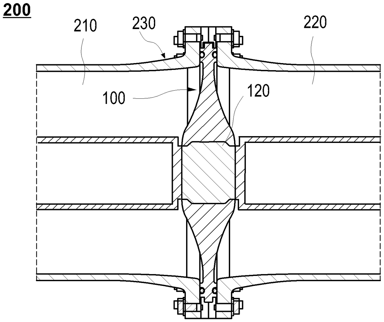
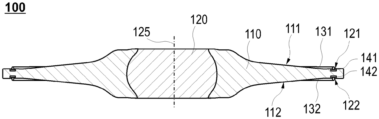
[0023] figure 1 A schematic cross-sectional view of the insulator 100 according to the embodiment described herein is shown. In particular, the insulator 100 described h...


PUM

PropertyMeasurementUnit
Surface roughnessaaaaaaaaaa

Abstract

An insulator (100) for installation in a high-voltage switching system is described. The insulator (100) includes an electrically insulating disc-shaped carrier element (110), wherein the carrier element (110) has a first disc-shaped surface (111) including a first groove (121) configured for accommodating a first sealing element (131) and an opposing second disc-shaped surface (112) including a second groove (122) configured for accommodating a second sealing element (132), wherein at least a bottom of the first groove (121) is provided by a first metallic element (141) embedded in the carrier element (110), and wherein at least a bottom of the second groove (122) is provided by a second metallic element (142) embedded in the carrier element (110).

Description

Technical field [0001] Embodiments of the present disclosure relate to the sealing of high voltage and high current systems. In particular, the embodiments of the present disclosure relate to the sealing of compartments of gas insulated switchgear (GIS) or generator circuit breakers (GCB). More specifically, the embodiments of the present disclosure relate to the sealing of an insulator provided in a compartment of an insulated switchgear or a generator circuit breaker. Background technique [0002] In gas-insulated switchgear and circuit breakers, at least one compartment must be sealed. Because the conductor must be insulated when it leaves the compartment, the insulator itself must be sealed between the two compartments or relative to the outside. Conventionally, EPDM (Ethylene Propylene Diene Monomer) rubber or acrylonitrile-butadiene rubber (NBR) sealing ring (such as a sealing O-ring) is used to achieve sealing. Therefore, depending on the material of the seals, differen...

Claims


Application Information

Patent Timeline
IPC IPC(8): H02B13/045
CPCH02B13/045H02G5/068
Inventor P.埃尔泽P.阿施万登A.里巴克A.西维克R.普拉特
Owner HITACHI ENERGY SWITZERLAND AG
Features
  • Generate Ideas
  • Intellectual Property
  • Life Sciences
  • Materials
  • Tech Scout
  • Unparalleled Data Quality
  • Higher Quality Content
  • 60% Fewer Hallucinations
Learn More