
Device and method for adsorption synergizing low temperature plasma to catalyze and treat waste gas

A low-temperature plasma and catalytic treatment technology, applied in separation methods, gas treatment, chemical instruments and methods, etc., can solve problems such as limited space, poor desorption and regeneration effect of adsorbent, and treatment.

Active Publication Date: 2018-10-12
CHONGQING UNIV
View PDF7 Cites 1 Cited by
  • Summary
  • Abstract
  • Description
  • Claims
  • Application Information

AI Technical Summary

Problems solved by technology

When the catalyst is placed inside the low-temperature plasma generator, in addition to using the long-lived active substances in the discharge plasma to degrade VOCs, it can also make full use of transient active substances to effectively degrade VOCs. The degradation efficiency is high, but there are Due to the limited internal space of the low-temperature plasma generator, the number of catalysts filled in it is limited, and there are by-products O 3 and NO x There are many shortcomings. Although the adsorbent is connected in series for secondary treatment, there is no measure for the thermal desorption regeneration of the adsorbent, and the effect of the desorption regeneration of the adsorbent is poor.

Method used


Image

  • Device and method for adsorption synergizing low temperature plasma to catalyze and treat waste gas
  • Device and method for adsorption synergizing low temperature plasma to catalyze and treat waste gas
  • Device and method for adsorption synergizing low temperature plasma to catalyze and treat waste gas

Examples


Embodiment Construction

[0063] The specific implementation manners of the present invention will be further described in detail below in conjunction with the accompanying drawings.

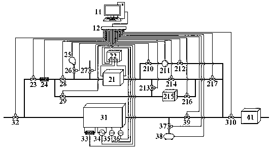
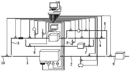
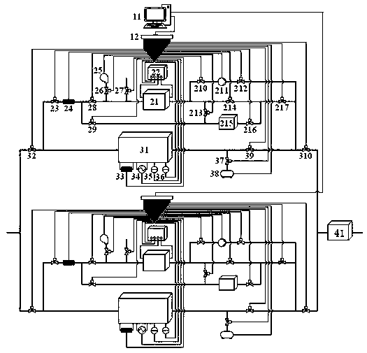
[0064] see figure 1 , figure 2 , a device for adsorbing and cooperating with low-temperature plasma catalytic treatment of exhaust gas, including an intake pipe 10, a first air pipe 1, an adsorption unit 31, a second air pipe 2, and an exhaust pipe 9 connected in sequence; the intake pipe 10 is provided with an intake switch Valve 32, the exhaust pipe 9 is provided with an exhaust switch valve 310; it also includes a plasma generation unit 21; the plasma generation unit 21 is connected to one end of the air intake pipe 10 connected to the first air pipe 1 through the third air pipe 3 Connect the exhaust pipe 9 to the end of the second air pipe 2 through the fifth air pipe 5 and the fifth on-off valve I 210, the suction compression pump mechanism 211 and the fifth on-off valve II 212 arranged in sequence on the fifth ai...


PUM


Abstract

The invention relates to a device and method for adsorption synergizing low temperature plasma to catalyze and treat waste gas. The device comprises an air inlet pipe, a first air pipe, an adsorptionunit, a second air pipe and an air exhaust pipe which are sequentially connected; switch valves are arranged on the air inlet pipe and the air exhaust pipe; the device further comprises a plasma generating unit and a desorption waste gas treatment unit; the plasma generating unit is connected with an air injection branch pipe, an air switch valve is arranged on the air injection branch pipe, the plasma generating unit is connected with the air exhaust pipe through a fifth air pipe and an air exhaust compression pump mechanism arranged on the fifth air pipe, and the air exhaust pipe is connected with a tail gas treatment unit; and an adsorption agent and a catalyst are arranged in the adsorption unit. The adsorption agent desorption and regeneration effect of the device is better, the degradation efficiency to VOCs (volatile organic chemicals) is higher, and the harmful substances and active substances in the tail gas are less; the problem that high-concentration waste gas is directly treated by a low temperature plasma generating unit and thus explosion risks exist is avoided, and the problems that the space is limited, and the by-products are more when the catalyst is placed in the low temperature plasma generating unit are avoided.

Description

technical field [0001] The invention belongs to the technical field of chemical purification of waste gas, and in particular relates to a device and method for adsorption and low-temperature plasma catalytic treatment of waste gas. Background technique [0002] Volatile organic pollution waste gas (hereinafter referred to as VOCs waste gas) is mostly produced in industrial production processes, such as paint production, chemical fiber industry, metal coating, chemical coatings, shoemaking and tanning, plywood manufacturing, tire manufacturing and other industrial production processes, among which Contains a large amount of volatile organic compounds (VOCs), mainly including acetone, toluene, phenol, dimethylaniline, formaldehyde, n-hexane, ethyl acetate, ethanol, etc., which are common air pollutants and endanger the health of exposed people . [0003] At present, there are two types of basic technologies for VOCs treatment. One is recycling technology. The basic idea of ​​...

Claims


Application Information

Patent Timeline
IPC IPC(8): B01D53/86B01D53/76B01D53/44
CPCB01D53/007B01D53/02B01D53/32B01D53/44B01D53/76B01D53/8687B01D2251/104B01D2257/708B01D2259/40088B01D2259/804B01D2259/818
Inventor 刘坤郑振峰
Owner CHONGQING UNIV
Learn More