
Semi-automatic machining equipment of steel materials

A kind of processing equipment and semi-automatic technology, which is applied in the field of mechanical processing equipment, can solve the problems of complexity, danger, and roughness of the end of the steel surface, and achieve the effects of high precision, improved precision, and saving manpower and resources

Active Publication Date: 2018-10-12
赣州溢之远钢材有限公司
View PDF2 Cites 7 Cited by
  • Summary
  • Abstract
  • Description
  • Claims
  • Application Information

AI Technical Summary

Problems solved by technology

Steel grinding is due to the fact that the surface of the steel is very rough due to the action of the cutting machine or other effects after processing, but the smoothness of the end of the steel is required during the use of many steels, and the surface or end of the steel It is not smooth, and workers are likely to cause cuts or abrasions to workers during the handling process, which is very dangerous. At present, integrated cutting and grinding machines are not popular in the market, and many integrated cutting and grinding machines require manual operation to move the specific position of the steel. In order to realize the function of cutting and polishing, it is very complicated and wastes manpower and resources

Method used


Image

  • Semi-automatic machining equipment of steel materials
  • Semi-automatic machining equipment of steel materials
  • Semi-automatic machining equipment of steel materials

Examples


Embodiment Construction

[0019] Below in conjunction with accompanying drawing and embodiment of description, specific embodiment of the present invention is described in further detail:

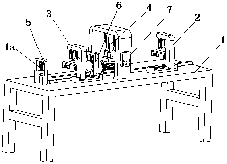
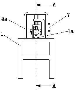
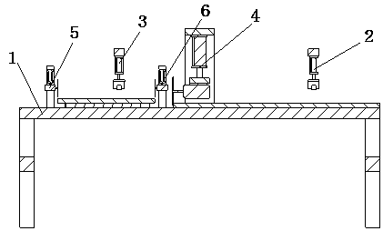
[0020] refer to Figure 1 to Figure 6 The shown semi-automatic steel processing equipment includes a base 1, a first grabbing assembly 2, a second grabbing assembly 3, a cutting assembly 4, a first grinding assembly 5 and a second grinding assembly 6, and the cutting assembly 4 is set In the middle part of the base 1, the first grabbing assembly 2 and the second grabbing assembly 3 are fixedly installed on the base 1 and located on the left and right sides of the cutting assembly 4. The first grabbing assembly 2 includes a first motorized Screw slide table 2a, inverted L-shaped first support frame 2b, first cylinder 2c, inverted U-shaped first clamping plate 2d, first clamping cylinder 2e and second clamping cylinder 2f, first electric wire The rod slide 2a is fixedly connected with the base 1, the first support fr...


PUM


Abstract

The invention relates to the field of machining apparatuses, in particular to semi-automatic machining equipment of steel materials. The semi-automatic machining equipment comprises a base, a first grabbing assembly, a second grabbing assembly, a cutting assembly, a first grinding assembly and a second grinding assembly, wherein the cutting assembly is arranged in the middle of the base; the firstgrabbing assembly and the second grabbing assembly are fixedly mounted on the base and are positioned on the left side and the right side of the cutting assembly; the first grinding assembly and thesecond grinding assembly are positioned on the same side of the cutting assembly and are positioned on the two sides of the second grabbing assembly; the first grinding assembly and the second grinding assembly are fixedly connected with the base, and a controller is also arranged on the cutting assembly; and the first grabbing assembly, the second grabbing assembly, the cutting assembly, the first grinding assembly and the second grinding assembly are electrically connected with the controller. According to the semi-automatic machining equipment of the steel materials disclosed by the invention, integration of cutting and grinding of the steel materials can be realized, and the precision of a product is higher under numerical control transportation.

Description

technical field [0001] The invention relates to the field of mechanical processing equipment, in particular to a semi-automatic processing equipment for steel materials. Background technique [0002] Steel structure cutting refers to the process of cutting and processing steel structures according to needs in industrial production. Steel grinding is due to the fact that the surface of the steel is very rough due to the action of the cutting machine or other effects after processing, but the smoothness of the end of the steel is required during the use of many steels, and the surface or end of the steel It is not smooth, and workers are likely to cause cuts or abrasions to workers during the handling process, which is very dangerous. At present, integrated cutting and grinding machines are not popular in the market, and many integrated cutting and grinding machines require manual operation to move the specific position of the steel. In order to realize the function of cuttin...

Claims


Application Information

Patent Timeline
IPC IPC(8): B23P23/04B23Q7/00B23Q7/04
CPCB23P23/04B23Q7/00B23Q7/04
Inventor 唐伟金卫明
Owner 赣州溢之远钢材有限公司
Learn More