
Control method and system for fan system of cremation equipment

A technology of fan system and control method, which is applied in the methods of incinerating corpses, burning methods, and burning equipment, etc., can solve the problems of waste of resources, large manpower, and accelerated wear and tear of equipment, so as to reduce injuries and save resources and manpower. Effect

Active Publication Date: 2019-06-07
民政部一零一研究所
View PDF3 Cites 1 Cited by
  • Summary
  • Abstract
  • Description
  • Claims
  • Application Information

AI Technical Summary

Problems solved by technology

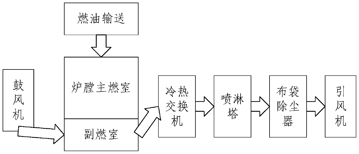
For example, in the induced air control system in the fan system, the induced air volume is mainly controlled by manually adjusting the opening of the smoke exhaust gate under the condition of the induced draft fan operating at full load. The frequent movement of the mechanical structure will cause the wear and tear of the equipment to be accelerated. On the other hand, since the induced draft fan is always in full-load operation, it will lead to unnecessary waste of electric energy.
Therefore, the manual control method in the prior art not only requires a lot of manpower, but also cannot accurately control the fan system based on manual control based on experience, so that electric energy and fuel cannot be effectively used, resulting in a waste of resources; in the process of manual control, The burning environment will also cause damage to the health of workers

Method used


Image

  • Control method and system for fan system of cremation equipment
  • Control method and system for fan system of cremation equipment
  • Control method and system for fan system of cremation equipment

Examples


Embodiment Construction

[0039] In order to make the purpose, technical solutions and advantages of the embodiments of the present invention clearer, the technical solutions in the embodiments of the present invention will be clearly described below in conjunction with the accompanying drawings in the embodiments of the present invention. Obviously, the described embodiments are the Some, but not all, embodiments are invented. Based on the embodiments of the present invention, all other embodiments obtained by persons of ordinary skill in the art without making creative efforts belong to the protection scope of the present invention.

[0040] At present, energy shortage and environmental pollution are two major worldwide problems that plague mankind. With the rapid development of the economy and the enhancement of people's awareness of environmental protection, solving these two problems has also begun to be put on the agenda. It has been nearly ten years since the concept of "energy saving and emiss...


PUM


Abstract

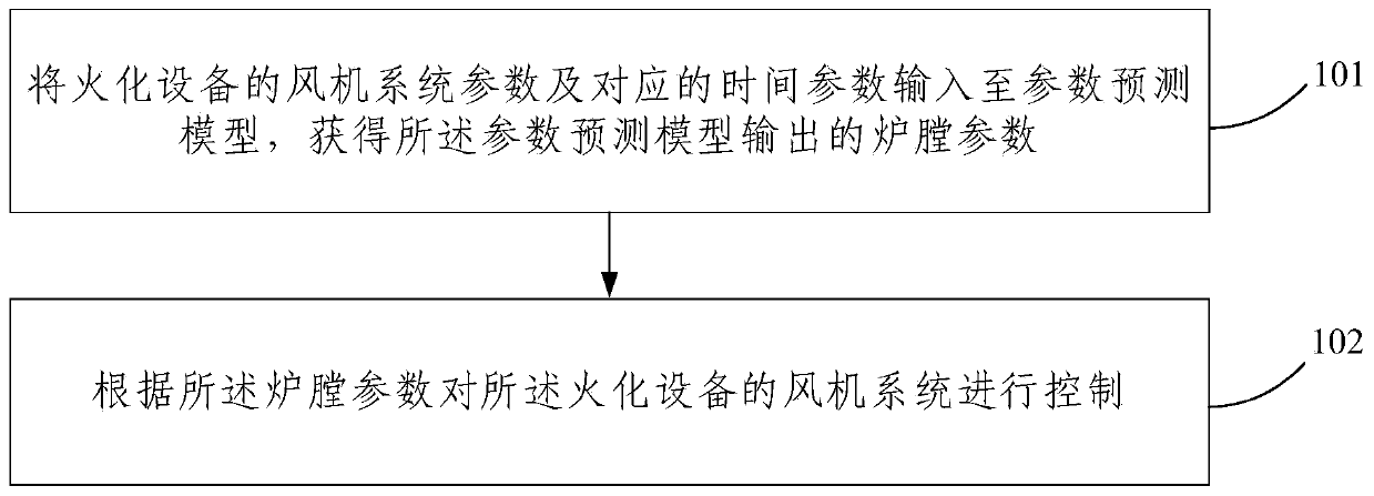
The embodiment of the invention provides a control method and system for a fan system of cremation equipment. The method comprises the steps that parameters of the fan system of the cremation equipment and corresponding time parameters are input into a parameter prediction model, and hearth parameters output by the parameter prediction model are acquired, wherein the parameter prediction model isacquired on the basis of training of sample time parameters, sample fan system parameters and corresponding sample hearth parameters; and the fan system of the cremation equipment is controlled according to the hearth parameters. According to the embodiment of the control method and system for the fan system of the cremation equipment, on the one hand, modeling is conducted through a neural network, and therefore the complex variation tendency between the fan system parameters and the hearth parameters in the cremation process can be expressed; on the other hand, the fan system can be automatically and accurately controlled on the basis of the hearth parameters; and compared with a manual control mode based on experience, resources and manpower are saved, and harm of the environment to bodies of workers is reduced.

Description

technical field [0001] Embodiments of the present invention relate to the field of cremation equipment, and more specifically, to a method and system for controlling a fan system of a cremation equipment. Background technique [0002] The production of cremation machines began in the late 1950s and early 1960s by imitating the Czech cremation machines. After that, on the basis of the Czech cremation machines, the Agricultural Machinery Gear Factory developed the CHL-2 cremation machine and gradually popularized it. This kind of cremation machine has uncontrolled combustion and serious smoke and dust emission pollution; the combustion space is too large, and the fuel consumption is relatively large; all manual operations consume a lot of physical strength of the workers. After the 1990s, cremation technology research and equipment manufacturing entered a period of vigorous development. Combustion technology, pollution treatment technology, computer technology, automatic cont...

Claims


Application Information

Patent Timeline
IPC IPC(8): F23G1/00F23L17/00
Inventor 方祥郭婵李秉杰李伯森
Owner 民政部一零一研究所
Learn More