Plating bath cathode wheel spraying-configured electric conduction device

A conductive device and cathode conductive technology, which is applied in the direction of current conduction device, electrode, electrolysis process, etc., can solve the problems of low electroplating efficiency, easy scrapping, and ruffles, so as to ensure the uniformity of electroplating, improve electroplating efficiency, and improve The effect of product yield

Pending Publication Date: 2018-10-12
捷成微系统(惠州)股份有限公司
View PDF8 Cites 1 Cited by
  • Summary
  • Abstract
  • Description
  • Claims
  • Application Information

AI Technical Summary

Problems solved by technology

[0012] The invention provides a high-performance electroplating tank cathode roller equipped with a spraying conductive device, which is composed of an undulating conductive roller and a spraying tube, which can effectively overcome the problem of scratches on the board surface in the prior art and electroplating problems caused by poor conductive contact. Problems such as low efficiency, poor plating uniformity, chemical solution pollution, easy scrapping of the board, and ruffles, etc., effectively ensure the plating uniformity, plating quality and plating effect, and at the same time improve the safety and plating efficiency of contact power supply during the plating process
The cathode roller of the electroplating tank of the present invention is equipped with a spray conductive device through the setting of the upper and lower undulating conductive rollers, and the upper and lower spray pipes and lower spray pipes on the upper and lower sides of the up and down undulating conductive roller, so that the conductive device forms a raised conductive roller. The cathode conductive device of the conductive plating tank of the spray device has the following advantages: 1. The undulating conductive roller can overcome the problem of the conductive brush scratching the board surface, and solve the problem of the conductive brush scratching the board surface 100%; 2. The undulating conductive roller It can solve the problems of low electroplating efficiency and poor electroplating uniformity caused by poor contact of conductive brushes, effectively improving electroplating efficiency by more than 90% and electroplating uniformity by more than 20%; The surface of the plate to be plated, or the shedding bristles enter the liquid medicine, causing the pollution of the liquid medicine; 4. The undulating conductive roll can solve the problem of scrap caused by the cathode clamping the edge of the plate, and effectively improve the product yield; 5. The undulating conductive roller can completely solve the lotus leaf problem caused by the cathode fixture; 6. In the present invention, the undulating cathode conductive roller adopts a conductive roller with ups and downs, and the wave-like path increases the contact area. The plate to be plated increases the contact strength between the conductive roller and the plate to be plated, which effectively improves the quality of electroplating and the effect of electroplating; The conductive roller and the lower conductive roller are sprayed with conductive liquid, which effectively increases the stability of conductivity, improves the uniformity of the plated plate, avoids scratching the plated plate, protects the plated plate, and effectively improves the plating efficiency by more than 50%.

Method used


Image

  • Plating bath cathode wheel spraying-configured electric conduction device
  • Plating bath cathode wheel spraying-configured electric conduction device
  • Plating bath cathode wheel spraying-configured electric conduction device

Examples


Embodiment Construction

[0031] In order to enable those skilled in the art to better understand the technical solution of the present invention, the product of the present invention will be further described in detail below in conjunction with the embodiments and accompanying drawings.

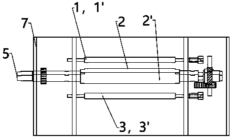
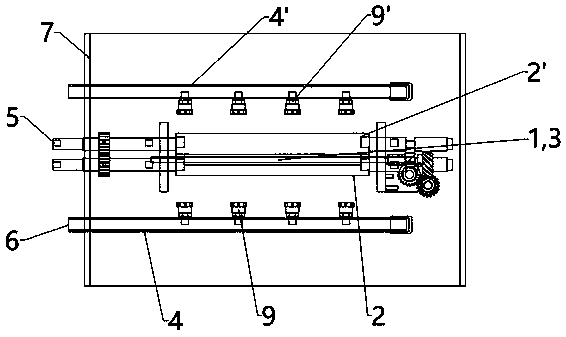
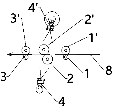
[0032] Such as Figure 1 to Figure 3As shown, an electroplating tank cathode roller is equipped with a spray conductive device, including an electroplating tank body 7, and a group of upper and lower undulating conductive rollers 2, 2' forming an undulating wave-like electroplating path are arranged inside the electroplating tank body 7 , are respectively the upper conductive roller 2' and the lower conductive roller 2, and one side of the upper conductive roller 2' and the lower conductive roller 2 is provided with a first group of upper and lower water retaining rollers 1, 1', and the upper conductive roller 2' and the other side of the lower conductive roller 2 are provided with a second set of upper and lower wat...


PUM

PropertyMeasurementUnit
diameteraaaaaaaaaa
thicknessaaaaaaaaaa

Abstract

The invention provides a plating bath cathode wheel spraying-configured electric conduction device which comprises a plating bath body. A set of upper and lower fluctuation electric conduction wheelsforming a fluctuation type wavy plating path are arranged in the plating bath body. First-grade upper and lower water blocking wheels are arranged on the left sides and the right sides of the upper and lower fluctuation electric conduction wheels correspondingly. An upper spraying pipe is arranged on the upper side of the upper fluctuation electric conduction wheel, and a lower spraying pipe is arranged on the lower side of the lower fluctuation electric conduction wheel. The upper spraying pipe and the lower spraying pipe are located on the corresponding positions of the outer sides of the upper fluctuation electric conduction wheel and the lower fluctuation electric conduction wheels and are used for spraying electric conduction liquid to the corresponding fluctuation electric conductionwheels. Gaps for a to-be-plated plating plate to pass through are formed between the corresponding upper wheels and lower wheels of the two sets of upper and lower water blocking wheels and one set of upper and lower fluctuation electric conduction wheels. The plating path of the to-be-plated plating plate is a fluctuation type wavy path. The plating bath cathode wheel spraying-configured electric conduction device has the beneficial effects that the electric conduction performance is good, and plating uniformity and plating current stability are good.

Description

technical field [0001] The invention relates to the technical field of a cathode roller conductive device in an electroplating device, in particular to a cathode roller of an electroplating tank equipped with a spray conductive device. Background technique [0002] Reel-to-roll electroplating line, in the prior art, for the cathode conductive device of the electroplating tank of the reel-to-roll electroplating line, the current manufacturer's design mainly adopts two conductive methods of cathode conductive brush and cathode clamp. [0003] 1. The conduction of the cathode conductive brush will cause the following problems: [0004] 1. If the strength of the conductive brush itself is too high, it will cause the conductive brush to scratch the surface of the electroplating plate, and the scratch rate of the product is over 90%. [0005] 2. If the strength of the conductive brush itself is too soft, the contact strength between the conductive brush and the plate to be plated...

Claims


Application Information

Patent Timeline
Patent Type & Authority Applications(China)
IPC IPC(8): C25D17/00C25D17/12C25D7/06
CPCC25D7/06C25D17/007C25D17/12
Inventor 郭立铭郭立德
Owner 捷成微系统(惠州)股份有限公司
Why Eureka
Try Eureka