
Single control energy-saving multi-layer hollow glass inlaid louver

An energy-saving, blinds technology, applied to windows/doors, door/window protection devices, shading screens, etc., can solve the problems of affecting the light transmission effect, the overall strength of the window is weak, and the operation is laborious, etc.

Pending Publication Date: 2018-10-12
JIANGSU SDL ENERGY CONSERVATION TECH CO LTD
View PDF21 Cites 12 Cited by
  • Summary
  • Abstract
  • Description
  • Claims
  • Application Information

AI Technical Summary

Problems solved by technology

However, the multi-layer hollow glass built-in venetian blind formed by this structure will cause the following confusion in the actual use process, that is, when it is installed in a building: between heat insulation and the operability of the controller to the venetian blind It is difficult to find a reasonable balance point, because if the venetian blind is arranged in the aforementioned inner hollow cavity, although it can be located in the inner hollow cavity in the traditional way by the manual operation control mechanism located on the side of the inner glass facing the indoor side of the building The flipping of the venetian blinds and the lifting control mechanism of the venetian blinds are operated to make the venetian blinds lift or turn the blinds as needed. However, since the venetian blinds are located in the inner hollow cavity, the outer hollow cavity has no effect on the partition due to the absence of the venetian blind. Thermal insulation has some effect
Conversely, if the venetian blind is placed in the outer hollow cavity, the heat insulation effect can be significantly improved, but the manual operation control mechanism located on the side of the inner glass facing the room cannot control the blind located in the outer hollow cavity through the inner hollow cavity. The flipping and lifting control mechanism of the venetian blind is operated, because the manual operation control mechanism and the flipping and lifting control mechanism of the venetian blind are magnetically attracted to each other through a piece of glass, which can be found in the Chinese invention. Patent application publication number CN104747054A (double-glazed built-in shutters)
Another factor is: from the decoration effect of the building and from the consideration of the user's actual use needs, it is the first choice to set the venetian blind in the outer hollow cavity, but due to structural limitations, it is impossible to manually install the venetian blind in the building. The operation control mechanism operates the curtain flipping and the venetian blind lifting control mechanism that is arranged in the outer hollow along with the venetian blind, which not only affects the improvement of the decoration effect of the building, but also limits the reasonable choice of the user.
[0009] The "energy-saving multi-layer hollow glass shutter" recommended by the invention patent authorization announcement number CN105041169B solves the above technical problems and objectively fulfills the technical effect summarized in paragraph 0021 of the specification, but there are still the following shortcomings: First, due to the The structure is unreasonable, so the airtightness and positioning effect of the glass, especially the medium glass, is relatively poor, and the overall strength of the window is relatively fragile; The two ends of the rope are fixedly connected to the curtain flip adjustment control mechanism of the double-control structure by knotting. If it is a single-control structure, since the curtain flip and the lifting of the venetian blind are controlled by an independent mechanism, the curtain flip And the venetian blind lifting control mechanism is responsible, so the two ends of the curtain flip traction rope are fixedly connected with the blind flip and venetian blind lifting control mechanism by knotting. The knotting is done by the workers manually, so it is inevitable The slack margin after knotting, so that the length of the curtain flipping traction rope between the two knotting points exceeds the length actually required by the process. Although the excess length is relatively limited, it has an effect on the flipping of the curtain But it will have a serious impact. On the other hand, after using for a period of time, the traction rope will elongate when the curtain is turned over, which will also affect the turning effect of the curtain.
In addition, there are similar problems with the lifting and lowering traction ropes of the venetian blinds (also known as "bottom traction ropes"); thirdly, due to the lack of reasonable moisture absorption measures, once the temperature difference between the interior and exterior of the building is large, there will be a gap between the inner glass and the middle glass. There is dew condensation in the inner hollow cavity and the outer hollow cavity between the outer glass and the middle glass, which affects the light transmission effect; Fourth, when the venetian blind is lifted and lowered every time, the venetian blind lifting traction rope will rub against the traction pulley, Therefore, it is not enough to really effectively protect the blind lifting traction rope and the traction pulley; Fifth, due to the many inflection points of the blind lifting traction rope, the lifting balance is relatively poor and the operation is relatively laborious

Method used


Image

  • Single control energy-saving multi-layer hollow glass inlaid louver
  • Single control energy-saving multi-layer hollow glass inlaid louver
  • Single control energy-saving multi-layer hollow glass inlaid louver

Examples


Embodiment Construction

[0029] In order to understand the technical essence and beneficial effects of the present invention more clearly, the applicant will describe in detail the following examples, but the descriptions of the examples are not intended to limit the solutions of the present invention. Equivalent transformations that are only formal but not substantive should be regarded as the scope of the technical solution of the present invention.

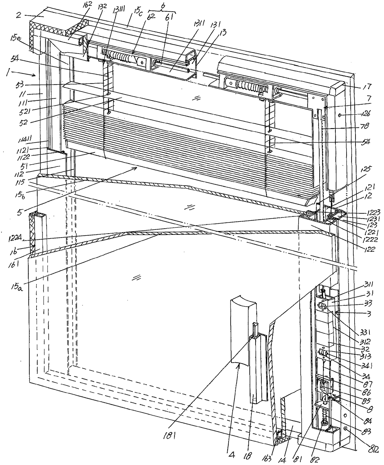
[0030] In the following descriptions, all concepts related to directionality or orientation of up, down, left, right, front and back are based on figure 1 The shown position status is a reference, so it cannot be understood as a special limitation on the technical solution provided by the present invention.

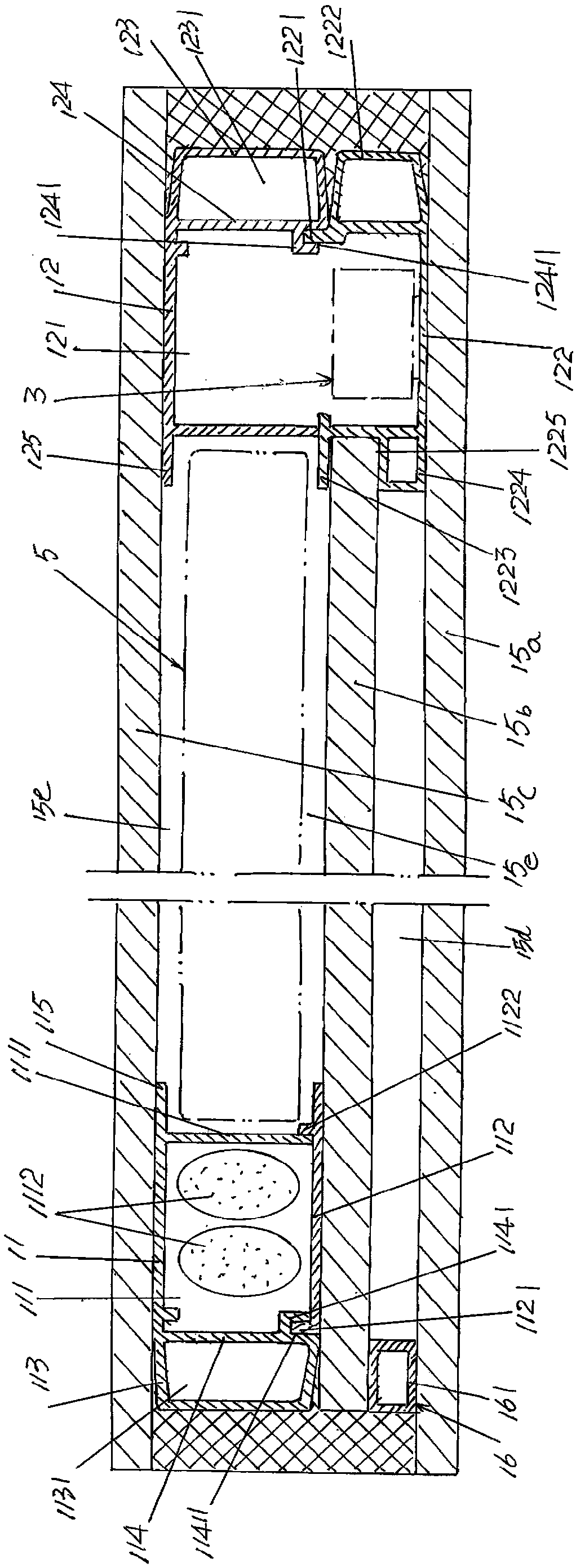
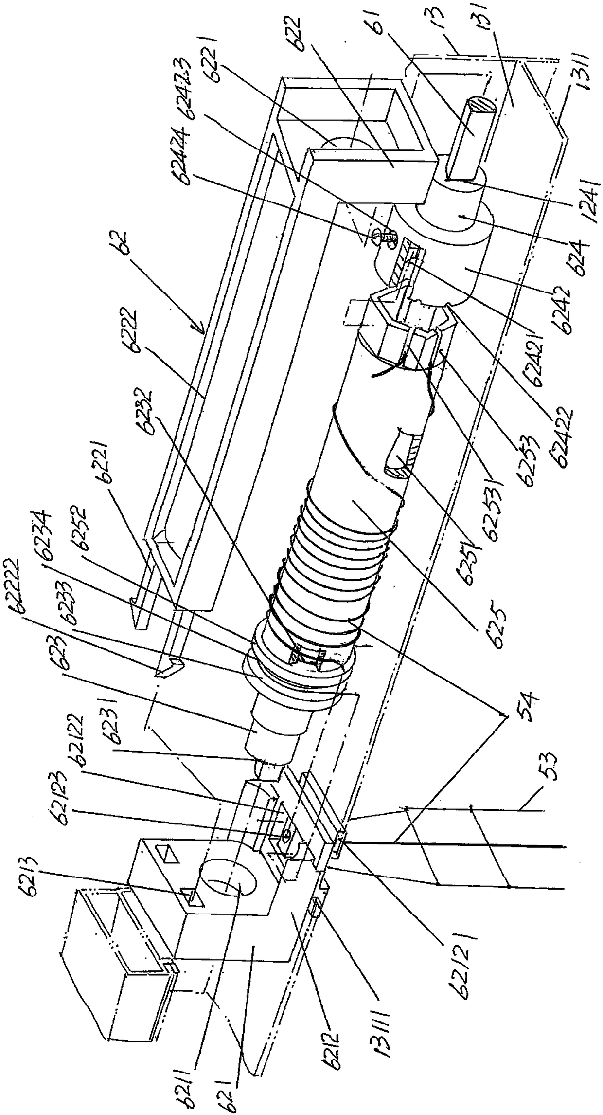
[0031] See Figure 1 to Figure 3 , shows the window 1, the window 1 includes a left vertical frame 11, a right vertical frame 12, an upper horizontal frame 13, a lower horizontal frame 14, an inner glass 15a, a middle glass 15b, an outer glass 15...


PUM


Abstract

The invention discloses a single control energy-saving multi-layer hollow glass inlaid louver. The single control energy-saving multi-layer hollow glass inlaid louver comprises a louver body; the louver body comprises a left longitudinal frame strip, a right longitudinal frame strip, an upper horizontal frame strip, a lower horizontal frame strip, inner glass, middle glass, outer glass, an inner hollow cavity partition frame, a curtain piece overturn and louver curtain lifting control mechanism a manual operation control mechanism, and a louver curtain and curtain piece overturn and louver curtain lifting mechanism. The louver is characterized by further comprising an expanding and fastening mechanism which is fixed in the right longitudinal frame strip, and is connected with an overturn shaft driving mechanism and the curtain piece overturn and louver curtain lifting control mechanism; a left longitudinal frame strip cavity covering plate is matched in a inserted mode with the left longitudinal frame strip; an upper horizontal frame strip covering plate is matched with the upper horizontal frame strip in an inserted mode; the curtain piece overturn and louver curtain lifting control mechanism comprises an overturn shaft and a pulling rope coiling device; the pulling rope coiling device comprises a first and second pulling rope coiling roll rotating shaft head bearing seats, afirst and second pulling rope coiling roll rotating shaft heads and a pulling rope coiling roll. Air impermeability and intensity of the louver body are improved; lifting is stable, the operation is easy and the driving effect to the overturning shaft is guaranteed.

Description

technical field [0001] The invention belongs to the technical field of hollow glass products, and in particular relates to a single-control energy-saving multi-layer hollow glass built-in shutter. Background technique [0002] The built-in shutters of insulating glass have the following self-evident advantages: good heat insulation to reflect the energy saving of the building; excellent sound insulation to avoid the disturbance of external noise; anti-condensation and frost to ensure sufficient indoor light and Reflect the expected bright effect; through the adjustment of the deflection angle of the venetian blinds, the required indoor lighting requirements can be obtained, privacy can be protected, and the curtains of the venetian blinds can be protected from dust, so as to reflect the excellent no-cleaning effect; It is ideal for embellishment of buildings to improve the grade of buildings; strong impact resistance, good safety and long service life to meet the installatio...

Claims


Application Information

Patent Timeline
IPC IPC(8): E06B9/264E06B9/32E06B9/322
CPCE06B9/264E06B9/32E06B9/322
Inventor 肖敏
Owner JIANGSU SDL ENERGY CONSERVATION TECH CO LTD
Learn More