Resonant Power Generation Hydraulic Drive Method and Device for Electric Vehicle Based on Leverage Effect
A power generation device, electric vehicle technology, applied in the direction of fluid pressure actuators, machines/engines, mechanisms that generate mechanical power, etc., can solve the impact of safety and cushioning comfort, vibration conduction resonance amplitude has no effective control means, Problems such as poor space compatibility of the resonance power generation device achieve the effects of optimized matching, easy control, and avoiding deterioration
- Summary
- Abstract
- Description
- Claims
- Application Information
AI Technical Summary
Problems solved by technology
Method used
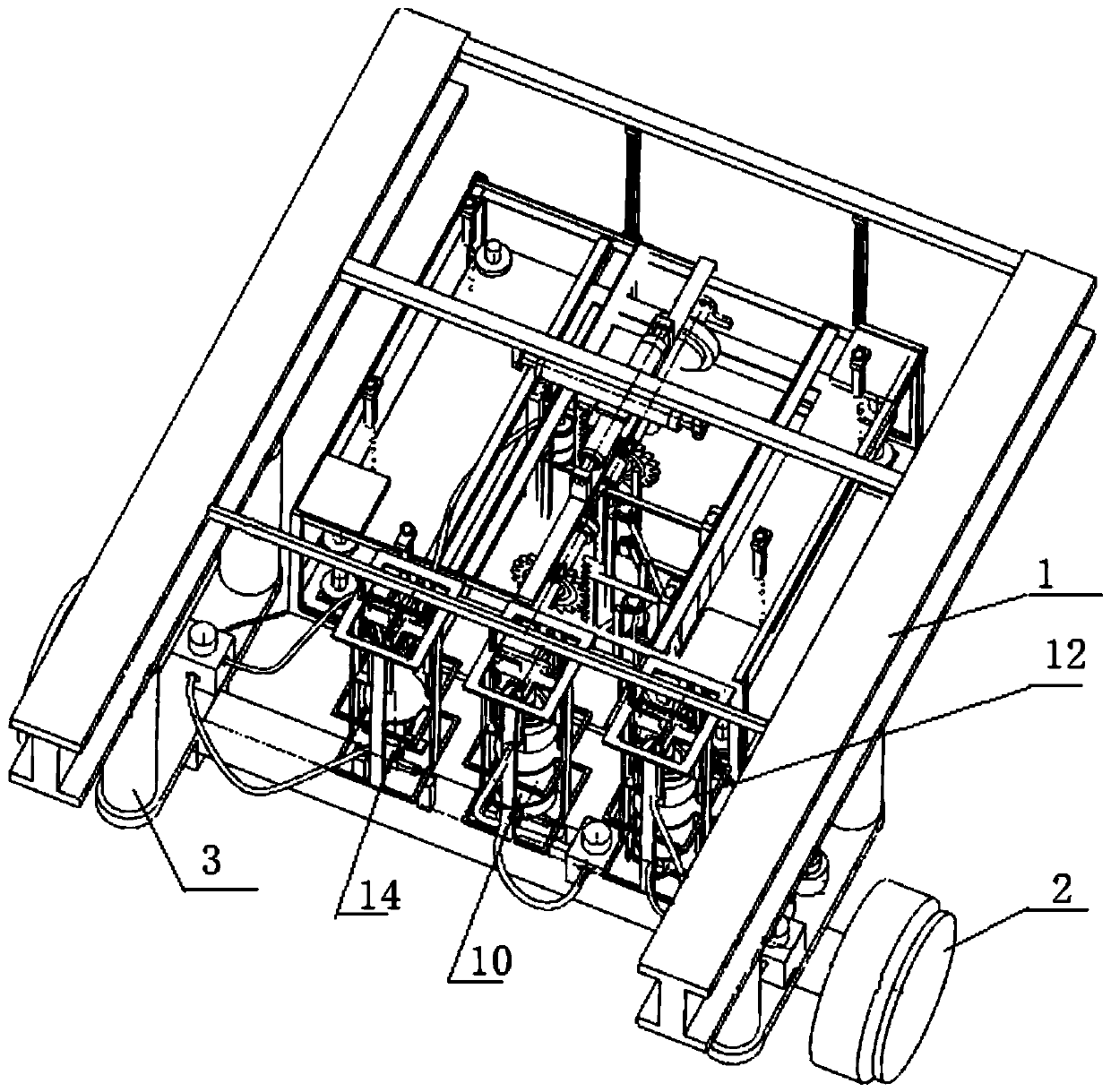
Image


Examples
Embodiment 1
[0037] Electric vehicle resonance power generation hydraulic drive device, the spur rack is driven by the piston rod of the driven hydraulic cylinder of the above-mentioned hydraulic system group, the hydraulic system group also includes the hydraulic cylinder installed on the axle, the piston rod of the hydraulic cylinder on the axle is connected to the body floor , to undertake the vibration of the sprung body, is the active hydraulic cylinder, conducts vibration transmission through the hydraulic circuit of the hydraulic system group and one or more slave hydraulic cylinders connected by the hydraulic circuit, and transmits the vibration to the hydraulic cylinder driven by the piston rod of the hydraulic cylinder The straight rack drives the central shaft of the generator to rotate, and each group of hydraulic system groups makes the hydraulic system group have a lever effect by setting hydraulic cylinders with different piston diameters, and the resonance force of the hollow...
Embodiment 2
[0047] In addition to the above-mentioned active hydraulic cylinders and slave hydraulic cylinders of each group, as well as the hydraulic oil circuit connecting the active hydraulic cylinders and slave hydraulic cylinders, the three groups of hydraulic system groups also include the upper oil chamber of the active hydraulic cylinders of each group The discharge pressure relief oil circuit of the active hydraulic cylinder connected with the lower oil chamber.
[0048] A split-throttle control valve is used on the two oil circuits of each group to control the respective flows of the two oil circuits, so that the flow of the hydraulic oil circuits connecting the active hydraulic cylinder and the slave hydraulic cylinder can be actively controlled. Then, through the control of the flow rate of the slave hydraulic cylinder, the moving speed of the spur rack is driven, that is, the rotation speed of the generator, so as to actively control the amount of power generation.
[0049] A...
PUM
 Abstract
Description
Claims
Application Information
 - R&D
- Intellectual Property
- Life Sciences
- Materials
- Tech Scout
- Unparalleled Data Quality
- Higher Quality Content
- 60% Fewer Hallucinations
Browse by: Latest US Patents, China's latest patents, Technical Efficacy Thesaurus, Application Domain, Technology Topic, Popular Technical Reports.
© 2025 PatSnap. All rights reserved.Legal|Privacy policy|Modern Slavery Act Transparency Statement|Sitemap|About US| Contact US: help@patsnap.com