
Tuning liquid column damper with multiple real-time adjustment damping

A technology for tuning liquid column damping and real-time adjustment, which is applied in the direction of shock absorbers, shock absorbers, springs/shock absorbers, etc., and can solve the problems of inability to adjust in real time, rapid adjustment of vibration intensity, and inability to realize super-high buildings and structures The most effective control of vibration and other issues to achieve the effect of ensuring safety and applicability, low energy consumption, and high damping adjustment accuracy

Pending Publication Date: 2018-10-12
HOHAI UNIV
View PDF0 Cites 10 Cited by
  • Summary
  • Abstract
  • Description
  • Claims
  • Application Information

AI Technical Summary

Problems solved by technology

However, the size of the water hole in the diaphragm of the existing tuned liquid column damper is fixed, and it cannot be quickly adjusted according to the size of the earthquake or strong wind suffered by the structure and the vibration intensity of the structure, and it is impossible to realize the adjustment of super high buildings and structures. The most effective control of vibration
Not only that, the liquid surface of the existing tuned liquid column damper is a free liquid surface, and the flow velocity under the action of external vibration is only related to the viscosity of the liquid itself, which cannot be adjusted in real time according to the needs of vibration reduction control

Method used


Image

  • Tuning liquid column damper with multiple real-time adjustment damping
  • Tuning liquid column damper with multiple real-time adjustment damping
  • Tuning liquid column damper with multiple real-time adjustment damping

Examples


Embodiment Construction

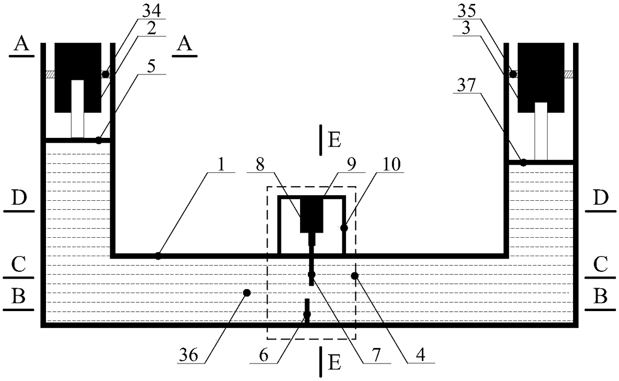
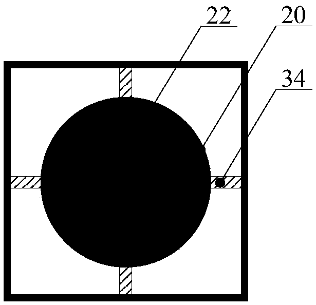
[0027] Such as Figure 1-8As shown, a tuned liquid column damper with multiple real-time damping adjustments includes: a U-shaped tubular water tank 1, a first magnetorheological damper 2, a second magnetorheological damper 3 and a water hole adjustment mechanism 4, the first The magnetorheological damper 2 is slidingly connected to the water tank 1 through the first water retaining plate 5, and the second magnetorheological damper 3 is slidingly connected to the water tank 1 through the second water retaining plate 37. The water tank 1 is filled with liquid 36, and the first The water retaining plate 5 and the second water retaining plate 37 are all located at the liquid level position of the vertical section of the U-shaped tubular water tank 1 with equal cross-section, and the shell 20 of the first magneto-rheological damper 2 is fixed on the water tank 1 through the first bracket 34, The housing 20 of the second magneto-rheological damper 3 is fixed on the water tank 1 thr...


PUM


Abstract

The invention discloses a tuning liquid column damper with multiple real-time adjustment damping. The tuning liquid column damper comprises a U-shaped pipe-shaped water tank, a first magneto-rheological damper, a second magneto-rheological damper and a water passing hole adjusting mechanism, the first magneto-rheological damper and the second magneto-rheological damper are internally provided withcurrent control systems, the water passing hole adjusting mechanism comprises a fixed transverse separating plate, a movable transverse separating plate, an ejection rod, a stepping motor and a fixedsupport, a U-shaped notch is arranged at the upper end of the fixed transverse separating plate, a semicircular notch is arranged at the lower end of the movable transverse separating plate, the U-shaped notch and the semicircular notch form a water passing hole, the movable transverse separating plate can freely move up and down, and a displacement adjusting system is arranged inside the stepping motor. By means of the tuning liquid column damper, damping force generated when liquid flows through the water passing hole during swing is used for reducing structural vibration, the current control systems are used for adjusting the liquid flowing speed, the displacement adjusting system is used for adjusting the size of the water passing hole, and the safety and applicability of ultrahigh buildings and constructions under various earthquake and strong breeze effects are guaranteed.

Description

technical field [0001] The invention belongs to the technical field of vibration control of civil engineering structures, in particular to a tuned liquid column damper for damping multiple real-time adjustments for reducing the vibration of super-high buildings and structures. Background technique [0002] The destructive power of earthquakes and strong winds is huge. According to statistics, the average annual loss caused by earthquakes and strong winds in the world is as high as hundreds of billions of dollars. 41% of my country's territory and more than 50% of cities are in earthquake intensity above 7 degrees, and the situation of earthquake resistance and disaster prevention is extremely severe. In recent years, with the development of the economy, a large number of super high buildings and structures have been built all over the country. The rigidity of these buildings and structures is small, and it is very easy to generate severe vibration due to the action of earth...

Claims


Application Information

Patent Timeline
IPC IPC(8): F16F9/53
CPCE04H9/02E04H9/0235F16F7/1017F16F2224/045
Inventor 周广东谢美希操声浪
Owner HOHAI UNIV
Learn More