Automatic inflation releasing device of shipborne sounding balloon

An air-exploration balloon and automatic inflation technology, which is applied in the container filling method, the container discharge method, the fixed-capacity air storage tank, etc., can solve the problems of complicated operation steps, inability to hold the balloon, and increase the pressure of personnel, so as to reduce the number of personnel. Use, improve work efficiency and practicability, and improve the effect of automation

Active Publication Date: 2018-10-12
THE FIRST INST OF OCEANOGRAPHY SOA +1
View PDF11 Cites 4 Cited by
  • Summary
  • Abstract
  • Description
  • Claims
  • Application Information

AI Technical Summary

Problems solved by technology

[0003] The commonly used traditional inflation mode is to first tighten the inflation port at the end of the balloon on the copper inflatable base connected to the helium cylinder through a rubber hose, then need 2-3 people to hold and stabilize the balloon, and one person to open the helium cylinder Inflate slowly. After the inflation is complete, carefully remove the balloon from the inflatable base, use a thin wire to tie the inflation port tightly and connect the sensor to release. The operation steps are cumbersome, which adds great pressure to the comprehensive survey voyage of the shift system. At the same time There is a situation that the balloon cannot be held due to strong wind, which leads to release failure or damage to the balloon

Method used


Image

  • Automatic inflation releasing device of shipborne sounding balloon
  • Automatic inflation releasing device of shipborne sounding balloon
  • Automatic inflation releasing device of shipborne sounding balloon

Examples


Embodiment Construction

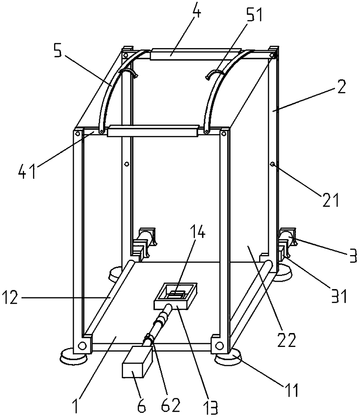
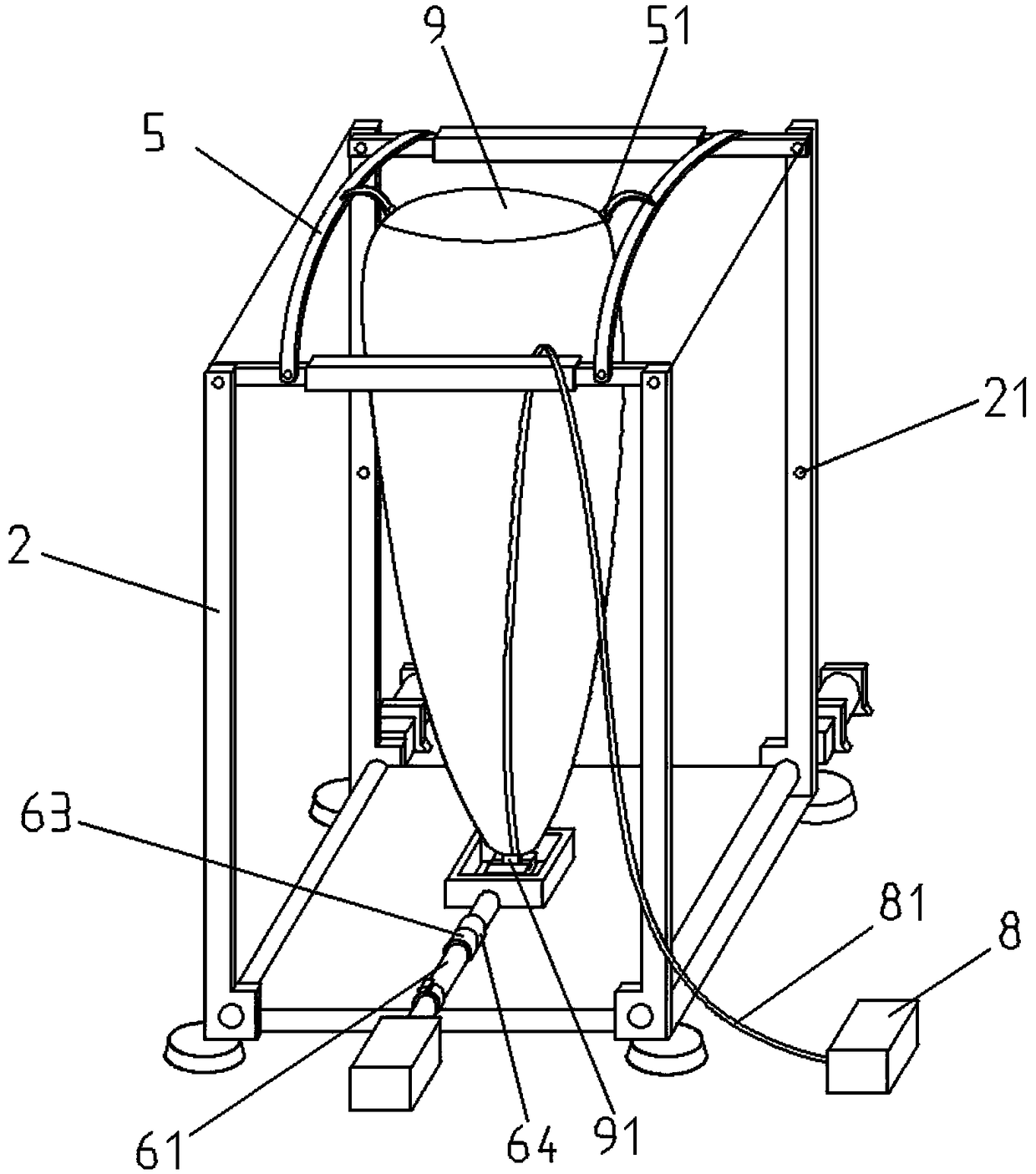
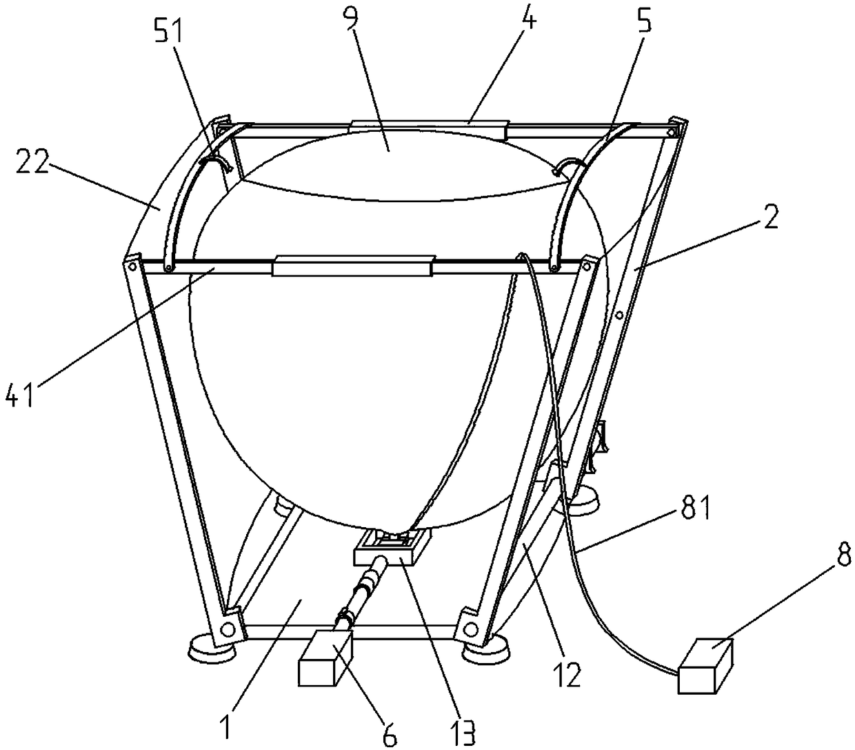
[0027] Such as Figure 1 to Figure 4 As shown, a ship-borne sounding balloon automatic inflation release device and its use method include a base frame 1, a fixed support 11, a rotating shaft 12, a mounting base 13, an electric lock 14, a rotating side frame 2, and an infrared sensing module 21 , elastic membrane 22, rotary motor 3, secondary reducer 31, telescopic rod body 4, extension rod 41, elastic limit belt 5, positioning clip 51, inflation source 6, transmission pipeline 61, pressure detection module 62, solenoid valve 63 , a flow controller 64, a control module 7, a data processing module 71, a fixed block 8, a rope 81, a balloon 9, an inflatable one-way valve 91, and the underframe 1 is installed through a plurality of fixed supports 11 provided at the bottom On the hull, a rotating shaft 12 is respectively arranged inside the two sides of the bottom frame 1, and a rotating side frame 2 is respectively arranged at both ends of the rotating shaft 12, and an elastic fil...


PUM


Abstract

The invention discloses an automatic inflation releasing device of a shipborne sounding balloon and belongs to the technical field of high-altitude aerological sounding. The automatic inflation releasing device comprises a balloon body, a bottom frame and an elastic limiting belt. An inflation one-way valve is arranged at the bottom of the balloon body. Rotating side frames are arranged on the twosides of the bottom frame. Infrared induction modules are arranged on the rotating side frames. A rotation motor is arranged at the outer portion of one side of each rotating side frame. The bottom frame is provided with an electric lock catch connected with the inflation one-way valve. A port of the inflation one-way valve is further connected with one end of a transmission pipeline. The other end of the transmission pipeline is provided with an inflation source, and an electromagnetic valve is arranged in the middle. The infrared induction modules are electrically connected with the input end of a control module, and the output end of the control module is electrically connected with the rotation motors, the electric lock catch and the electromagnetic valve. The problem that the lift-off automation degree of an existing sounding balloon is low is solved, the function of stabilizing the sounding balloon in the charging process can be achieved, meanwhile, use of personnel in the operation process is effectively reduced, the automation degree is high, and the working efficiency and practicability are greatly improved.

Description

technical field [0001] The invention relates to an automatic inflation and release device for a ship-borne sounding balloon and a use method thereof, belonging to the technical field of high-altitude meteorological detection. Background technique [0002] At present, sounding balloons are usually filled with hydrogen, helium and other gases inside, carry instruments into the sky and send the measured meteorological data back to the ground by radio, so as to conduct high-altitude meteorological observations. In existing marine survey voyages, sounding balloons are usually launched at a fixed time every day, so they often encounter situations where the sea wind is strong and the ship is swaying severely. [0003] The commonly used traditional inflation mode is to first tighten the inflation port at the tail of the balloon on the copper inflatable base connected to the helium cylinder through a rubber hose, then need 2-3 people to hold and stabilize the balloon, and one person ...

Claims


Application Information

Patent Timeline
Patent Type & Authority Applications(China)
IPC IPC(8): F17C5/06F17C7/00F17C13/02
CPCF17C5/06F17C7/00F17C13/025F17C2250/072Y02A90/30
Inventor 王冠琳滕飞江志辉李淑江
Owner THE FIRST INST OF OCEANOGRAPHY SOA
Why Eureka
Try Eureka