

Soil pollution detection apparatus
A detection device and soil pollution technology, applied in the field of soil diagnosis, can solve problems such as affecting detection accuracy and being prone to damage, and achieve the effects of improving detection accuracy, reducing impact and improving operational convenience
- Summary
- Abstract
- Description
- Claims
- Application Information
AI Technical Summary
Problems solved by technology
Method used
Image

Examples
Embodiment 1
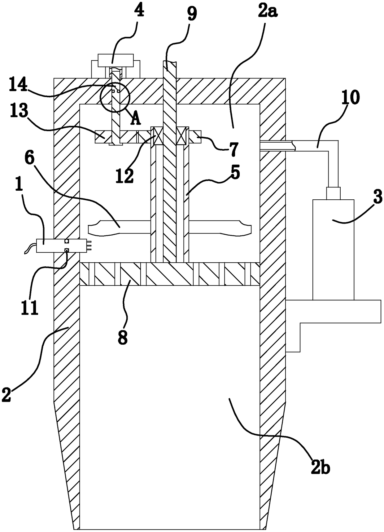
[0026] Such as figure 1 and figure 2 As shown, the soil pollution detection device is composed of a detection probe 1, a hollow straight rod-shaped retrieving rod 2, an air pump 3, a motor 4, a connecting pipe 5, a stirring blade 6, a transmission mechanism, and a driven gear 7.
[0027] Specifically, the top and bottom of the retrieving rod 2 are closed and open respectively, and the retrieving rod 2 is provided with a filter plate 8 that can slide up and down, and the side wall of the filter plate 8 is offset against the inner side wall of the retrieving rod 2. , The filter plate 8 divides the cavity of the retrieving rod 2 into an upper cavity 2a and a lower cavity 2b, and the upper cavity 2a and the lower cavity 2b are communicated through the filter holes on the filter plate 8 . Wherein, a screw rod 9 is vertically arranged in the upper cavity 2a, and the lower end of the screw rod 9 is fixedly connected with the filter plate 8, and a threaded hole opposite to the screw...
Embodiment 2
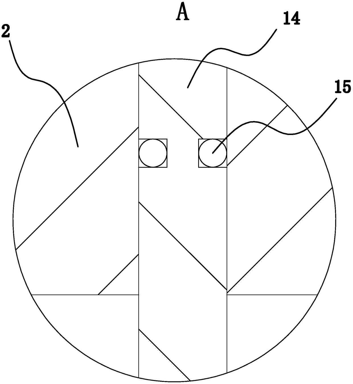
[0033] The structure and principle of this second embodiment are basically the same as that of the first embodiment, except that the transmission mechanism includes a main gear 13 and a drive shaft 14, the drive shaft 14 is vertically arranged in the upper cavity 2a, and the main gear 13 is sleeved and It is fixed outside the lower end of the drive shaft 14, and the main gear 13 and the driven gear 7 are meshed. The upper end of the drive shaft 14 stretches out the material rod 2, and the drive shaft 14 is axially fixedly connected with the material rod 2 through the bearing 12. During actual use, manually rotate the drive shaft 14 to drive the stirring blade 6 to stir the soil.
PUM
 Abstract
Description
Claims
Application Information