
Laser radar signal transition area correction method

A laser radar and signal transition technology, applied to radio wave measurement systems, instruments, etc., can solve the problems of small receiving angle, inconsistency of real atmospheric signals, and reduce the accuracy of laser radar, so as to expand the effective detection range and improve accuracy Effect

Inactive Publication Date: 2018-10-12
无锡中科光电技术有限公司 +1
View PDF2 Cites 1 Cited by
  • Summary
  • Abstract
  • Description
  • Claims
  • Application Information

AI Technical Summary

Problems solved by technology

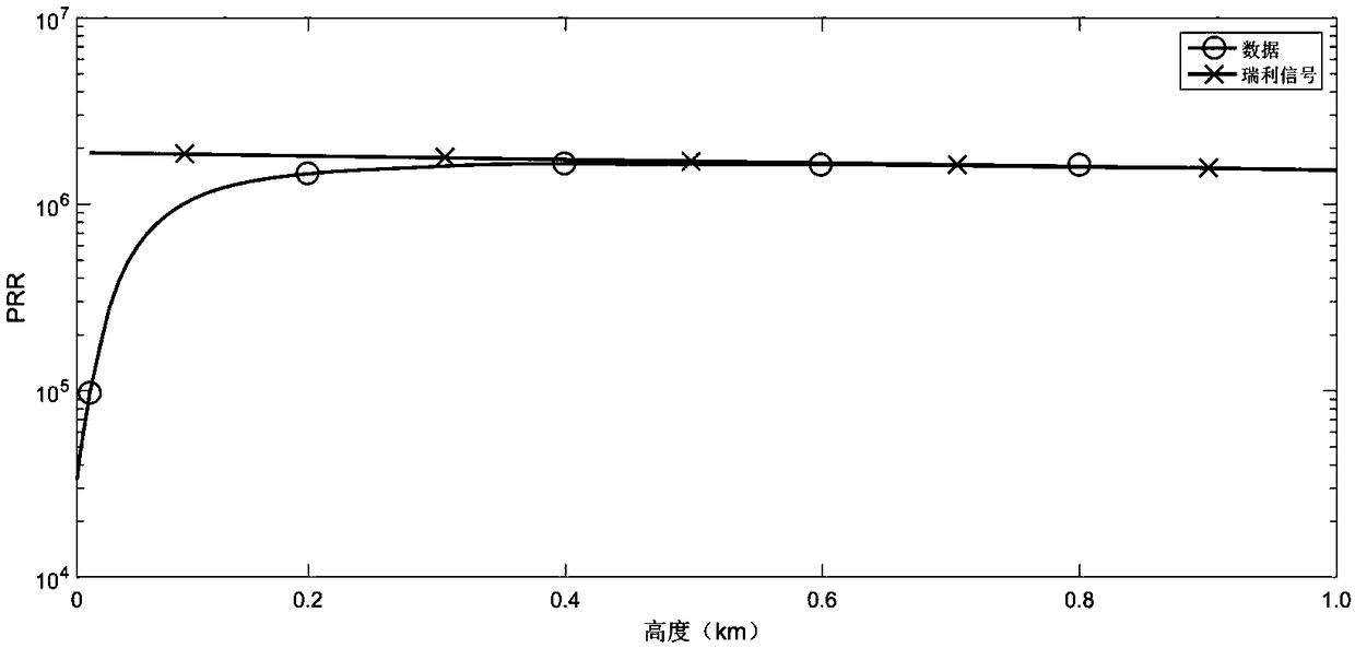
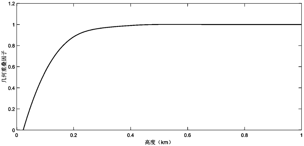
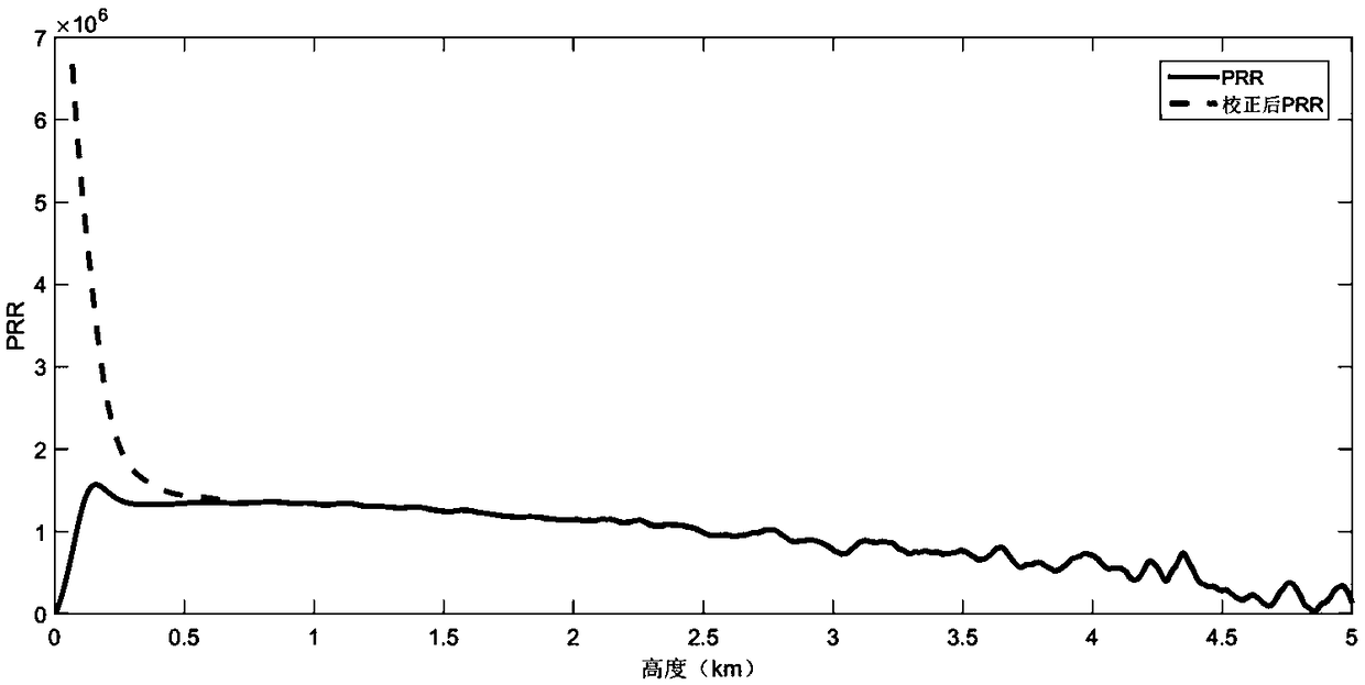
[0003] The current laser radar mainly adopts a fold-back optical path structure, but the receiving angle of this structure is small, resulting in the inability to receive all low-altitude signals, resulting in inconsistencies between the echo signal in the transition zone (usually 300 meters to 500 meters) and the real atmospheric signal , which greatly reduces the accuracy of lidar detection in the near-field area

Method used


Image

  • Laser radar signal transition area correction method
  • Laser radar signal transition area correction method
  • Laser radar signal transition area correction method

Examples


Embodiment

[0037] The method for correcting the laser radar signal transition area according to the embodiment of the present invention, the correction method for the laser radar signal transition area includes the following steps:

[0038] The laser radar equation corresponding to the backscattered echo signal of the m-scattering lidar is:

[0039]

[0040] Among them: P(z) is the backscatter echo signal received by the lidar at height z (unit, W); c is the laser radar system constant (unit, W km3 sr), β(z) is height z The total backscatter coefficient at (unit km-1·sr-1), and β(z)=β m (z)+β a (z), β m (z) and β a (z) respectively represent the backscattering coefficient of atmospheric molecules and the backscattering coefficient of aerosol; α(z) is the total extinction coefficient at distance z (unit, km-1) and α(z)=α m (z)+α a (z), α m (z) and α a (z) represent the extinction coefficient of atmospheric molecules and the extinction coefficient of aerosols respectively, and th...


PUM


Abstract

The invention discloses a laser radar signal transition area correction method comprising the following steps that the method is based on the laser radar of the coaxial detection module, the near-field signal is corrected by calibrating the transition area signal, noise filtering of the signal is performed in the process by using the Savitzky-Golay filter and geometric overlap factor calibration is performed on the transition area signal so as to perform better inversion of the spatial-temporal evolution of the near surface pollutants. The laser radar signal transition area correction method can be widely applied to detection of the laser radar to the atmospheric pollutants.

Description

technical field [0001] The invention belongs to laser radar, and in particular relates to a correction method for a laser radar signal transition area. Background technique [0002] Because the laser light source has the characteristics of good monochromaticity, strong coherence, high collimation, high brightness, and high power, lidar technology has developed rapidly in the fields of atmosphere, environment, and meteorology. Lidar is a detection device with laser as the light source. When the laser beam emitted by it is transmitted in the atmosphere, it is attenuated by the atmosphere on the transmission path (mainly from the extinction of atmospheric aerosol molecules and air molecules), and part of it is absorbed by the aerosol The laser scattered by the air molecules returns along the original path, and is attenuated by the atmosphere on the transmission path again, and finally received by the lidar. [0003] The current laser radar mainly adopts a fold-back optical pat...

Claims


Application Information

Patent Timeline
Patent Type & Authority Applications(China)
IPC IPC(8): G01S7/497
CPCG01S7/497
Inventor 万学平高洁张天舒刘文清李岭刘胜利
Owner 无锡中科光电技术有限公司
Learn More