Powder box for printer

A technology for printers and toner cartridges, which is applied in the fields of electrical recording technology using charge graphics, equipment for using electrical recording technology using charge graphics, and electrical recording technology. Unable to know the quantity and other problems, to achieve the effect of guaranteeing the printing effect, improving the cleaning efficiency and effect, and improving the cleaning efficiency

Active Publication Date: 2018-10-12
贵州省仁怀市西科电脑科技有限公司
View PDF7 Cites 5 Cited by
  • Summary
  • Abstract
  • Description
  • Claims
  • Application Information

AI Technical Summary

Problems solved by technology

[0005] The purpose of the present invention is to solve the problems in the prior art that the remaining amount of the toner cartridge cannot be known and the residual old toner affects the printing quality

Method used


Image

  • Powder box for printer
  • Powder box for printer

Examples


Embodiment Construction

[0020] Further detailed explanation through specific implementation mode below:

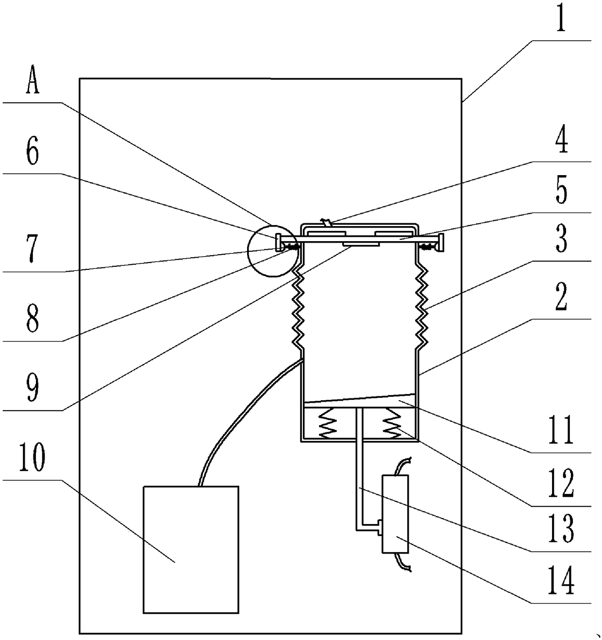
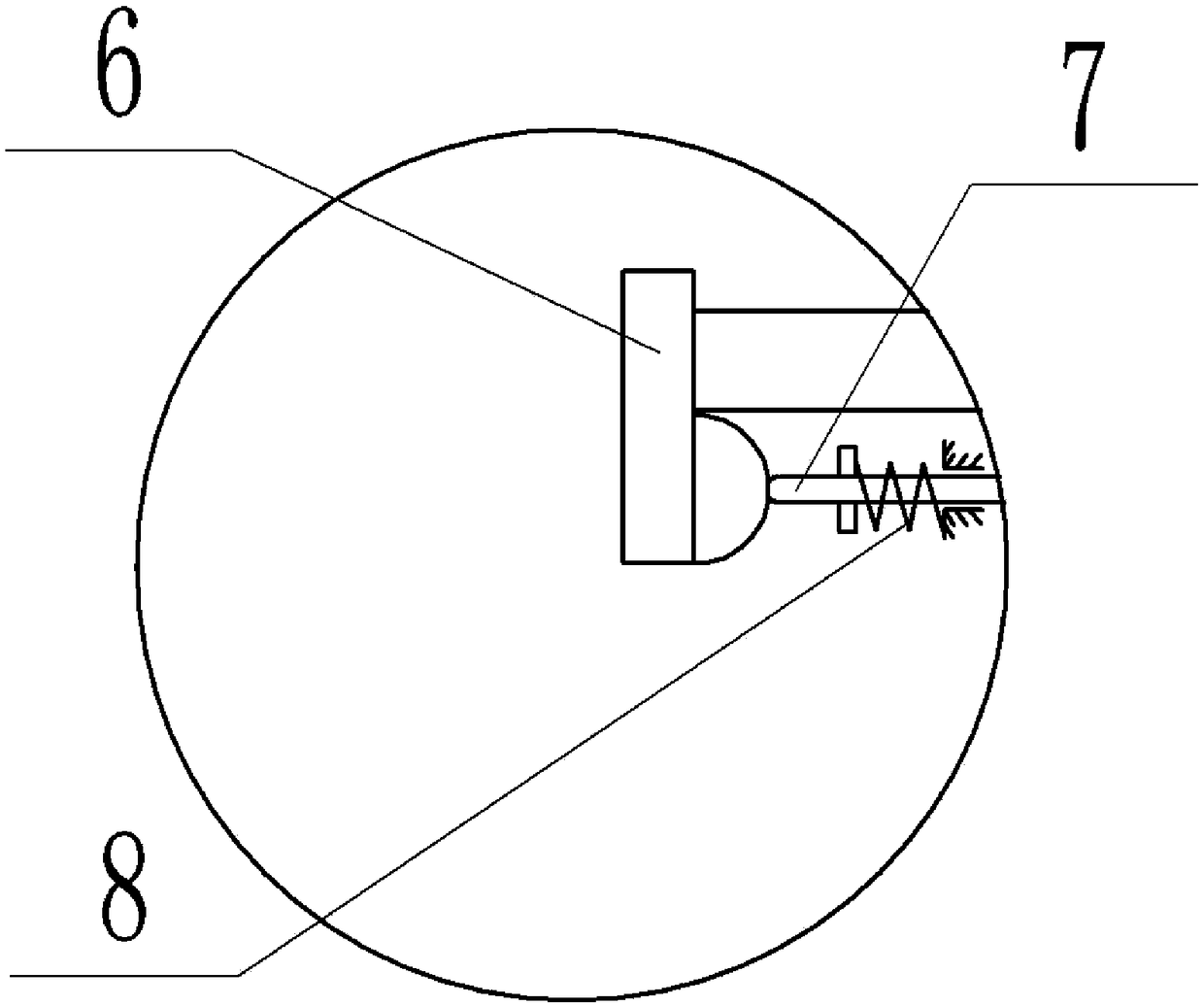
[0021] The reference signs in the drawings of the specification include: powder box body 1, powder bin 2, corrugated section 3, air intake pipe 4, rotating shaft 5, cam 6, ejector rod 7, first spring 8, blade 9, waste powder bin 10 , Piston plate 11, second spring 12, push rod 13, sliding rheostat 14.

[0022] The implementation of a kind of printer powder box is as figure 1 with figure 2 As shown: it includes the powder box body 1, the powder box body 1 is provided with a powder bin 2 and a waste toner bin 10, and the powder bin 2 and the waste toner bin 10 are connected through a pipeline, and a solenoid valve is arranged on the pipeline.

[0023] The powder box body 1 also includes an air intake pipe 4 distributed from top to bottom along the powder bin 2, a rotating shaft 5, a corrugated section 3, a piston plate, a second spring 12, a push rod 13 and a sliding rheostat 14, and the top of ...


PUM


Abstract

The invention relates to the field of printer equipment, in particular to a powder box for a printer. The powder box for the printer comprises a powder box body, wherein a powder bin and a waste powder bin are arranged in the powder box body and are communicated with each other through a pipeline; an electromagnetic valve is arranged on the pipeline; the powder box body also comprises an air inletpipe, a rotary shaft, a corrugated section, a piston plate, a second spring, a push rod and a slide rheostat distributed from top to bottom along the powder bin; a feed inlet is arranged on the top part of the powder bin; one end of the air inlet pipe is communicated with an air pump; the other end of the air inlet pipe is communicated with the top part of the powder bin; a plurality of blades are uniformly distributed on a part, located in the powder bin, of the rotary shaft along the axial direction; two ends of the rotary shaft stretch out of the powder bin and are connected with the powder bin in a rotary seal way. According to the scheme, through the linkage between various structures, the amount of residual carbon powder is displayed, the old carbon powder is removed, and the residues of the old carbon powder is prevented from influencing the printing quality.

Description

technical field [0001] The invention relates to the field of printer equipment. Background technique [0002] The toner cartridge is a container of toner used in laser printers. It is responsible for converting the light signal transmitted by the laser into a toner image composed of toner particles, and cooperates with the transfer roller to transfer the toner image to the paper. The traditional toner cartridge is mainly composed of a charging roller, a photosensitive drum, a magnetic roller, a powder knife, a cleaning blade, a toner bin, and a waste toner bin. The working process of traditional laser printers can be divided into 7 steps: charging, exposure, development, transfer, fixing, cleaning, and power elimination. Among them, the five steps of charging, exposure, development, cleaning, and power elimination are carried out around the traditional toner cartridge. . [0003] The details are as follows: (1) Charging: First, the photosensitive drum is charged by the cha...

Claims


Application Information

Patent Timeline
Patent Type & Authority Applications(China)
IPC IPC(8): G03G15/08G03G21/10G03G21/12
CPCG03G15/0896G03G21/105G03G21/12
Inventor 余洪科刘秋余忠保
Owner 贵州省仁怀市西科电脑科技有限公司
Why Eureka
Try Eureka