
Microphone

A microphone and cantilever technology, applied in sensor parts, magnetic field-controlled resistors, sensors, etc., can solve the problems of overall performance changes, limit the high signal-to-noise ratio performance of microphones, and yield loss, and achieve the effect of improving the signal-to-noise ratio.

Active Publication Date: 2018-10-12
WEIFANG GOERTEK MICROELECTRONICS CO LTD +1
View PDF4 Cites 4 Cited by
  • Summary
  • Abstract
  • Description
  • Claims
  • Application Information

AI Technical Summary

Problems solved by technology

During fabrication, variations in the mechanical properties (mechanical sensitivity, resonant frequency, curvature, etc.)
[0004] In addition, when the diaphragm vibrates, air flow resistance in gaps or perforations due to air viscosity becomes the dominant factor in MEMS microphone noise, limiting the microphone's high SNR performance

Method used


Image

  • Microphone
  • Microphone
  • Microphone

Examples


Embodiment Construction

[0025] In order to make the technical problems solved by the present invention, the technical solutions adopted, and the technical effects obtained easy to understand, the specific implementation manners of the present invention will be further described below in conjunction with the specific drawings.

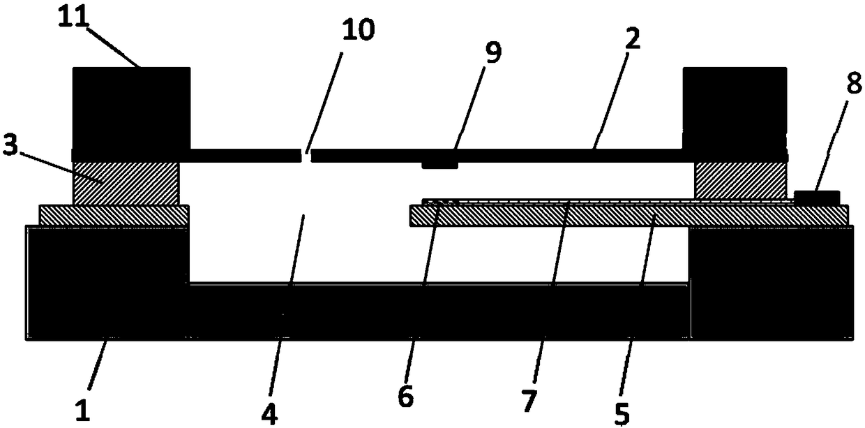
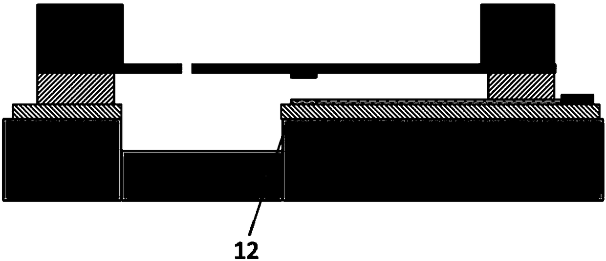
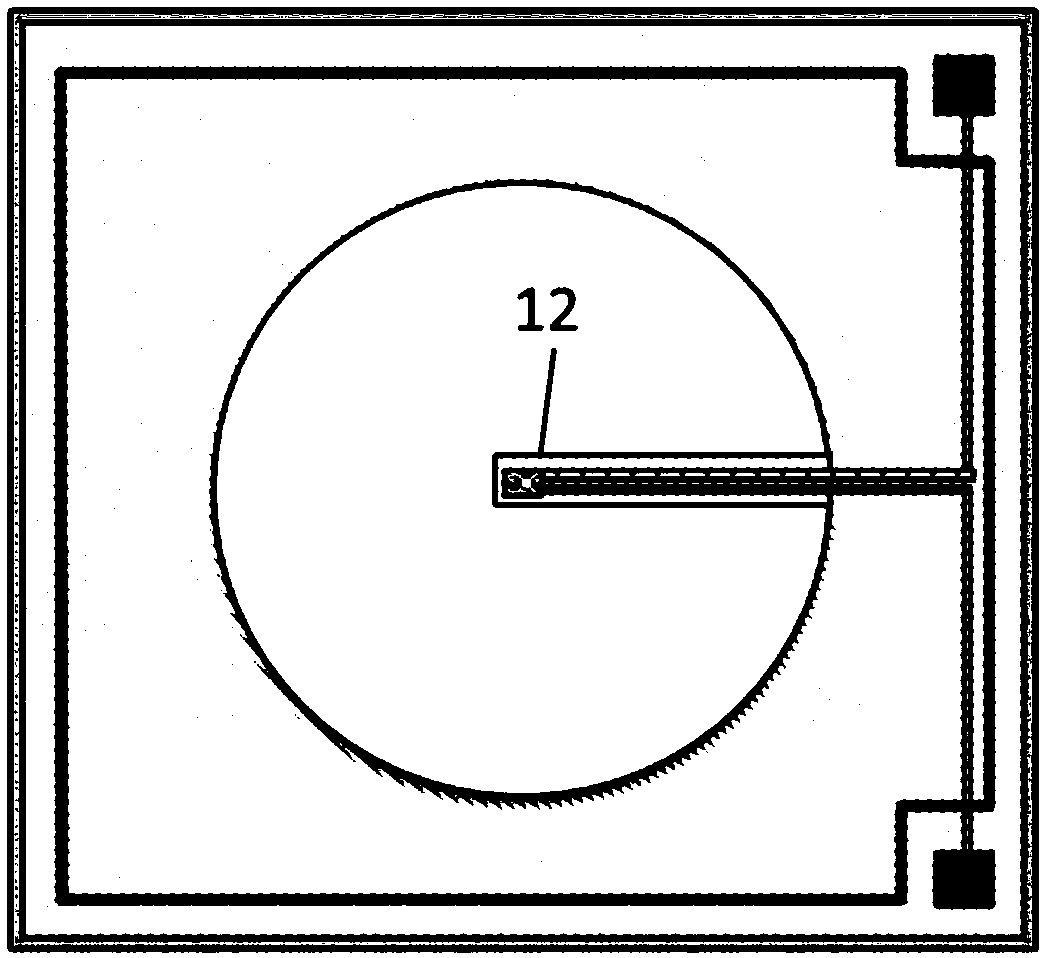
[0026] refer to figure 1 , the present invention provides a microphone, which includes a first substrate 1 , a diaphragm 2 and at least one cantilever 5 located on the first substrate 1 .

[0027] The first substrate 1 has an inner cavity with an open end, and the edge of the diaphragm 2 and the end of the cantilever 5 are directly or indirectly connected to the first substrate 1, so that the main part of the diaphragm 2 and the cantilever 5 is suspended on the first substrate 1. above the substrate 1 cavity.

[0028] The cantilever 5 and the diaphragm 2 are separated by a spacer 3 , and the height of the spacer 3 is the initial gap between the diaphragm 2 and the cantilever ...


PUM


Abstract

The invention discloses a microphone. The microphone comprises a first substrate with an inner cavity with an opened end, and further comprises a vibrating diaphragm and at least one cantilever arranged on the first substrate and suspended at the upper side of the inner cavity; the cantilever and the vibrating diaphragm are separated through an interval part, and the vibrating diaphragm and the inner cavity of the first substrate form an acoustic sealing cavity in a surrounding way; and a detection structure is arranged on the vibrating diaphragm and the cantilever. By adopting the cantileverstructure design, the space between the vibrating diaphragm and the cantilever is opened, and the airflow can smoothly pass through the cantilever when the vibrating diaphragm is in vibration, therebygreatly improving the signal-to-noise ratio of the microphone. Furthermore, the vibrating diaphragm and the inner cavity of the first substrate form the acoustic sealing cavity in the surrounding way, the air elasticity in the acoustic sealing cavity leads the sensitivity of the whole microphone; in the manufacturing the microphone, the parameter consistency of the acoustic sealing cavity can beeasily controlled, and the sensitivity consistency of the microphone can be guaranteed.

Description

technical field [0001] The present invention relates to the field of acoustic-electric conversion, more specifically, to a microphone mechanism, especially a microphone structure with high SNR. Background technique [0002] The current mainstream MEMS microphones all adopt a capacitive sensing structure, including a substrate, a back plate and a diaphragm formed on the substrate, and there is a gap between the back plate and the diaphragm, so that the back plate and the diaphragm form a A flat-plate capacitor sensing structure is established, and a cavity is formed between the back plate and the diaphragm. In order to equalize the pressure, dense through holes are usually designed on the back plate and the diaphragm. [0003] In a microphone with this structure, the mechanical sensitivity of the diaphragm dominates the sensitivity of the entire microphone. During fabrication, variations in the mechanical properties of the diaphragm (mechanical sensitivity, resonant frequen...

Claims


Application Information

Patent Timeline
IPC IPC(8): H04R19/04
CPCH04R19/04H04R2201/003H04R19/005H04R23/00H10N50/10
Inventor 邹泉波冷群文王喆
Owner WEIFANG GOERTEK MICROELECTRONICS CO LTD
Learn More