Honey production apparatus and usage method thereof

A production device and honey technology, applied in separation methods, chemical instruments and methods, evaporation, etc., can solve problems such as waste of resources, poor concentration effect, etc.

Active Publication Date: 2018-10-16
门源兴农蜂业有限公司
View PDF4 Cites 4 Cited by
  • Summary
  • Abstract
  • Description
  • Claims
  • Application Information

AI Technical Summary

Problems solved by technology

[0004] In the existing honey production process, the condensed water with high temperature in the evaporator is directly drained without being utilized, resulting in a waste of resources; in addition, because the honey is relatively viscous, in the falling film evaporator, the honey Can not enter the heating tube more evenly, resulting in poor concentration effect

Method used


Image

  • Honey production apparatus and usage method thereof
  • Honey production apparatus and usage method thereof
  • Honey production apparatus and usage method thereof

Examples


Embodiment 1

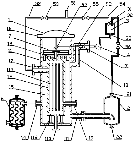
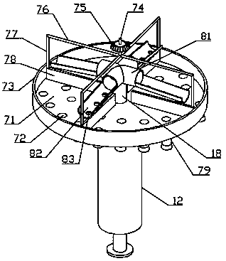
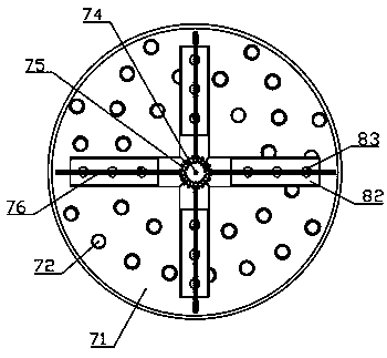
[0048] Such as Figure 1 to Figure 3 and Figure 6 , Figure 7 As shown, a honey production device of the present invention includes an evaporator (1), a separator (2) and a steam delivery pipeline, and a steam mixer is sequentially connected between the evaporator (1) and the separator (2) (3) and compressor (4), the third valve (56) is connected between the separator (2) and the steam mixer (3), and the evaporator (1) is also connected with a heat exchanger (6 );

[0049] The steam delivery pipeline includes a main pipe (51), a first branch pipe (52) is connected between the main pipe (51) and the evaporator (1), and a first valve ( 53), a second branch pipe (54) is connected between the main pipe (51) and the steam mixer (3), and a second valve (55) is connected to the second branch pipe (54);

[0050] In this embodiment, the evaporator (1) includes an outer shell (11) and an inner shell (12), so that the rising film evaporation and falling film evaporation are designed...

Embodiment 2

[0065] Such as Figure 4 and Figure 5 As shown, in this embodiment, the difference from Embodiment 1 is that the evaporator (1) includes a shell (114), and the top of the shell (114) is connected with a shell top (16), so A partition (10) is installed vertically in the middle of the housing (114), and a fourth feed liquid outlet (101) is arranged on the top of the partition (10), and the partition (10) connects the inside of the housing (114) Part of it is a left cavity and a right cavity. The upper part of the left cavity is provided with a first steam inlet (17), and the first steam inlet (17) is connected to the first branch pipe (52). The lower part of the left cavity A first condensed water outlet (14) is provided, the first condensed water outlet (14) is connected to the heat exchanger (6), the bottom of the left cavity is provided with a feed liquid inlet (110), and the left cavity is installed There is a first heating pipe (113); the upper part of the right cavity i...


PUM


Abstract

The invention belongs to the technical field of honey production equipment, and specifically relates to a honey production apparatus. The honey production apparatus comprises an evaporator, a separator and a steam-conveying pipeline; the evaporator is connected with the separator; a steam mixer and a compressor are orderly connected between the evaporator and the separator; a secondary steam outlet is arranged at the top of the separator; a third material-liquid outlet is arranged at the bottom of the separator; a third valve is connected between the separator and the steam mixer; the steam-conveying pipeline comprises a main pipe; a first branch pipe is connected between the main pipe and the evaporator; a first valve is connected onto the first branch pipe; a second branch pipe is connected between the main pipe and the steam mixer; a second valve is connected onto the second branch pipe; and the evaporator is further connected with a heat exchanger. The invention further discloses ausage method of the honey production apparatus. The honey production apparatus integrates functions of a rising-film evaporator and a falling-film evaporator, so that good evaporation effects are achieved; moreover, produced condensate water can be reused so as to achieve the goal of saving energy.

Description

technical field [0001] The invention belongs to the technical field of honey production equipment, and in particular relates to a honey production device and a using method thereof. Background technique [0002] Honey is the nectar that bees collect from the flowers of flowering plants and brewed in the hive. Bees take nectar or secretions with a water content of about 75% from the flowers of plants and store them in their second stomach. Under the action of various transformations in the body, they repeatedly brew various vitamins, minerals and When the amino acid is enriched to a certain value, at the same time, the polysaccharide in the nectar is converted into simple sugar glucose and fructose that can be directly absorbed by the human body. The water content is less than 23%, stored in the nest, and sealed with beeswax. Honey is a supersaturated solution of sugar, which will crystallize at low temperature. The crystallized part is glucose, and the non-crystallized part...

Claims


Application Information

Patent Timeline
Patent Type & Authority Applications(China)
IPC IPC(8): A23L21/25B01D1/22
CPCA23L21/25B01D1/22
Inventor 赵栋帮刘彩虹
Owner 门源兴农蜂业有限公司
Why Eureka
Try Eureka