Detection method and device of resonance frequency of ultrasonic transducer and ultrasonic transducer

A technology of ultrasonic transducer and resonant frequency, applied in the direction of measuring ultrasonic/sound wave/infrasonic wave, measuring device, adopting electrical device, etc., to achieve the effect of small error and easy determination of error range

Active Publication Date: 2018-10-16
CHONGQING XISHAN SCI & TECH
View PDF2 Cites 18 Cited by
  • Summary
  • Abstract
  • Description
  • Claims
  • Application Information

AI Technical Summary

Problems solved by technology

But in practice, the difference between the current in the output loop collected at the frequency near the resonant frequency and the current in the output loop collected at the resonant frequency is small, especially in the case of external interference, which will lead to There is a large error between the determined operating frequency and the actual resonant frequency
[0006] In view of the existence of the above-mentioned defect that there may be a large error between the operating frequency set by the ultrasonic transducer and the actual resonant frequency in the prior art, how to quickly and accurately determine the operating frequency of the ultrasonic transducer is currently a technical problem in the art. Technical problems to be solved by people

Method used


Image

  • Detection method and device of resonance frequency of ultrasonic transducer and ultrasonic transducer
  • Detection method and device of resonance frequency of ultrasonic transducer and ultrasonic transducer
  • Detection method and device of resonance frequency of ultrasonic transducer and ultrasonic transducer

Examples


Embodiment 1

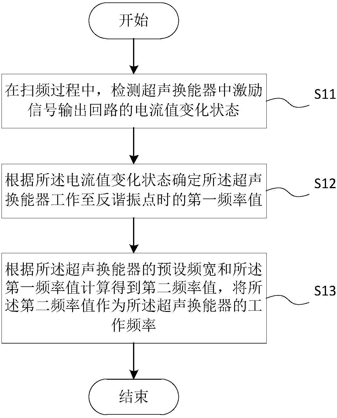
[0031] According to the first aspect of the present invention, this embodiment provides a method for detecting the resonance frequency of an ultrasonic transducer, see figure 1 , the detection method comprises the following specific steps:

[0032] S11, during the frequency sweeping process, detecting the change state of the current value of the excitation signal output loop in the ultrasonic transducer.

[0033] In this step, the excitation signal output loop (hereinafter also referred to as: loop or output loop) refers to the excitation power output system that transmits the excitation signal to the electric energy storage element in the ultrasonic transducer to cause the electric field or magnetic field to change and generate vibration.

[0034] Among them, if the operating frequency of the ultrasonic transducer is the resonant frequency, the performance of the entire ultrasonic system is the best, so how to accurately find the resonant frequency of the ultrasonic transduce...

Embodiment 2

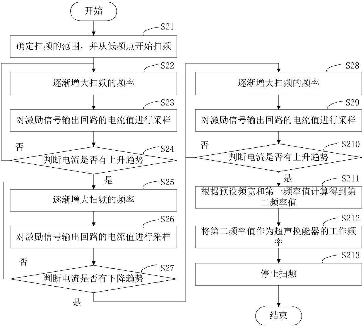
[0050] According to the first aspect of the present invention, it can be seen that the method of gradually increasing the output frequency of the excitation signal from low to high can better protect the ultrasonic transducer, which is a preferred implementation mode, so this embodiment will combine the frequency sweep process and figure 1 The described method, more specifically a detection method for the resonance frequency of an ultrasonic transducer, is given in image 3 , the detection method comprises the following specific steps:

[0051] S21. Determine the range of the frequency sweep, and start the frequency sweep from a low frequency point.

[0052] Wherein, the real resonance frequency of the ultrasonic transducer should be within the range of the set frequency sweep.

[0053] S22. Gradually increase the range of the frequency sweep.

[0054] S23, sampling the current value of the excitation signal output loop.

[0055] S24, judging whether the current has an upwa...

Embodiment 3

[0069] According to the second aspect of the present invention, this embodiment also provides a detection device for the resonant frequency of the transducer, see Figure 4 , the detection device 300 includes a frequency sweep module 310, a first frequency detection module 320 and a second frequency detection module 330, wherein the frequency sweep module 310 is used to detect where the excitation signal in the ultrasonic transducer is during the frequency sweep process The current value change state of the loop; the first frequency detection module 320 is used to determine the first frequency value when the ultrasonic transducer works to the anti-resonance point according to the current value change state; the second frequency detection module 330 is used to A second frequency value is calculated according to the preset bandwidth of the ultrasonic transducer and the first frequency value, and the second frequency value is used as the working frequency of the ultrasonic transdu...


PUM


Abstract

The invention provides a detection method and device of the resonance frequency of an ultrasonic transducer and the ultrasonic transducer. The detection method of the resonance frequency of the ultrasonic transducer comprises the following steps that 1, in a frequency sweeping process, a current value change state of an excitation signal output loop in the ultrasonic transducer is detected; 2, a first frequency value of the ultrasonic transducer when the ultrasonic transducer works to the anti-resonance point is determined according to the current value change state; and 3, calculating is carried out to obtain a second frequency value according to the preset frequency width and the first frequency value of the ultrasonic transducer, and the second frequency value is taken as the working frequency of the ultrasonic transducer. Compared with the prior art, the accuracy that the working frequency detected by the detection method is the resonance frequency of the ultrasonic transducer ishigher. In addition, the detection device and the ultrasonic transducer corresponding to the detection method have the same functions and effects.

Description

technical field [0001] The invention relates to the technical field of ultrasonic transducers, in particular to a method and device for detecting the resonant frequency of the ultrasonic transducer and the ultrasonic transducer. Background technique [0002] An ultrasonic transducer is a device that converts input electrical power into mechanical power (ie, ultrasound), including but not limited to medical devices such as ultrasonic bone knives. When the ultrasonic transducer is working, its best working frequency (ie, resonant frequency) is generally found by sweeping the frequency. [0003] In the prior art, the method for determining the resonance frequency may specifically have the following two methods: [0004] The phase detection scanning method scans the frequency of the output circuit within a certain range. When the phase of the current and voltage in the output circuit is the same, record the output frequency at that moment as the resonance frequency (operating f...

Claims


Application Information

Patent Timeline
Patent Type & Authority Applications(China)
IPC IPC(8): B06B1/02G01H11/06
CPCB06B1/0207G01H11/06
Inventor 郭毅军付健陈建赵正温兴东陈勤秦勇
Owner CHONGQING XISHAN SCI & TECH
Why Eureka
Try Eureka