
Ground slurry mixing system and method for TBM tunnel duct piece back grouting

A technology of back grouting and tunnel segment, applied in chemical instruments and methods, cement mixing devices, batching weighing instruments, etc., can solve the problems of insufficiency, low cement efficiency, construction stoppage, etc., to eliminate dust pollution, improve The effect of mixing quality and improving mixing efficiency

Pending Publication Date: 2018-10-16
THE THIRD ENG CO LTD OF CCCC SECOND HIGHWAY ENG BUREAU
View PDF0 Cites 0 Cited by
  • Summary
  • Abstract
  • Description
  • Claims
  • Application Information

AI Technical Summary

Problems solved by technology

The first traditional slurry mixing method needs to set up the mixing function area, bagged cement storage area and other areas in the limited space of the supporting trolley, which occupies the already narrow space resources; the second supporting slurry mixing equipment is limited by space. , the capacity of the mixing tank is small, and the amount of one-time mixing often cannot meet the needs of single-ring grouting construction, causing construction to stop and affecting construction efficiency; third, only manpower can be used to put in bagged cement, which is very easy to put in during the putting process. Dust pollution is generated, which damages the health of workers; Fourth, the efficiency of manual cement injection is low, and the amount of cement input is easily affected by human factors, resulting in inaccurate slurry mix ratios

Method used


Image

  • Ground slurry mixing system and method for TBM tunnel duct piece back grouting
  • Ground slurry mixing system and method for TBM tunnel duct piece back grouting
  • Ground slurry mixing system and method for TBM tunnel duct piece back grouting

Examples


Embodiment Construction

[0023] The present invention will be clearly and completely described below in conjunction with the accompanying drawings, so that those skilled in the art can fully implement the present invention without creative work.

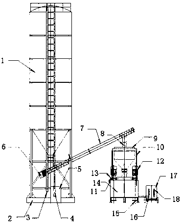
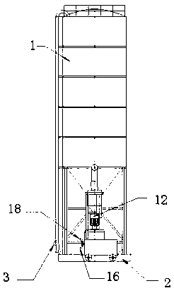
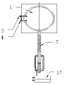
[0024] The specific embodiment of the present invention is: as Figure 1-3 As shown, a ground grouting system for back grouting of TBM tunnel segments, including cement tanker, high-pressure pumping pipe, bulk cement storage system, cement delivery system, cement weighing system, cement slurry mixing system, slurry delivery system System, slurry storage tank, PLC control system 11, the bulk cement storage system is set on the concrete foundation 2, the bulk cement storage system includes a cement silo 1, a dust removal oil barrel 5, and the cement silo 1 is provided with a pumping port 3 and the exhaust port 4, the cement tanker is connected with the pump material port 3 on the cement silo 1 through a high-pressure pumping pipe, and the cement silo 1 is conn...


PUM


Abstract

The invention provides a ground slurry mixing system and method for TBM tunnel duct piece back grouting. The system comprises a cement tank car, a high-pressure pumping pipe, a bulk cement storage system, a cement conveying system, a cement weighing system, a cement slurry mixing system, a slurry feeding system, a slurry storage tank and a PLC control system. The bulk cement storage system is arranged on a concrete foundation, and comprises a cement bin and a dustproof oil drum. A material pumping opening and an exhaust opening are formed in the cement bin, the cement tank car is connected with the material pumping opening in the cement bin through the high-pressure pumping pipe, the cement bin is connected with the dustproof oil drum through an exhaust pipe, and dust-containing waste gasin the cement bin is filtered out. The cement conveying system comprises a screw conveyer and a conveyer motor. The cement weighing system comprises a weighing hopper. The cement slurry mixing systemcomprises a stirring drum and a stirring motor. The slurry feeding system comprises a grouting machine. Slurry mixing is completed on the ground, the slurry mixing efficiency and quality are improved,and dust harm to workers is avoided.

Description

technical field [0001] The invention belongs to the technical field of slurry mixing systems, and in particular relates to a ground slurry mixing system and method for back grouting of TBM tunnel segments. Background technique [0002] The traditional cement slurry mixing process during TBM grouting construction adopts the method of installing slurry mixing equipment on the supporting trolley, and manually injecting clean water and bagged cement into the slurry mixing tank for mixing, which has four major drawbacks. The first traditional slurry mixing method needs to set up the mixing function area, bagged cement storage area and other areas in the limited space of the supporting trolley, which occupies the already narrow space resources; the second supporting slurry mixing equipment is limited by space. , the capacity of the mixing tank is small, and the amount of one-time mixing often cannot meet the needs of single-ring grouting construction, causing construction to stop ...

Claims


Application Information

Patent Timeline
IPC IPC(8): B28C5/08B28C7/04B28C7/06B28C7/12B28C7/16
CPCB28C5/08B28C7/044B28C7/06B28C7/12B28C7/16
Inventor 史经峰张玄王青波施昌平
Owner THE THIRD ENG CO LTD OF CCCC SECOND HIGHWAY ENG BUREAU
Learn More