
Die cutting method and device for conductive cloth with ultra-thin single-sided adhesive layer

A single-sided adhesive, conductive cloth technology, applied in lamination devices, chemical instruments and methods, lamination and other directions, can solve the problems of large processing errors, low accuracy, low production efficiency, etc., to reduce production costs and improve production. High efficiency and high machining accuracy

Active Publication Date: 2018-10-16
上海昊佰智造精密电子股份有限公司
View PDF17 Cites 7 Cited by
  • Summary
  • Abstract
  • Description
  • Claims
  • Application Information

AI Technical Summary

Problems solved by technology

Since the lamination of the ultra-thin single-sided adhesive layer and the conductive cloth surface layer is done manually by the operator, the lamination process only relies on visual observation and manual lamination operation, resulting in large processing errors, low accuracy, and product defect rate. Up to 50%, increasing the production cost, and the production efficiency is low, it is difficult to meet the requirements

Method used


Image

  • Die cutting method and device for conductive cloth with ultra-thin single-sided adhesive layer
  • Die cutting method and device for conductive cloth with ultra-thin single-sided adhesive layer
  • Die cutting method and device for conductive cloth with ultra-thin single-sided adhesive layer

Examples


Embodiment 1

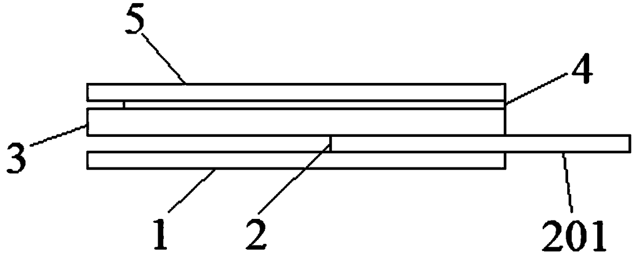
[0050] A die-cutting method of conductive cloth with ultra-thin single-sided adhesive layer, such as figure 1 As shown, the conductive cloth includes a conductive cloth layer protective film 1, a blue film layer 2, a conductive cloth layer 3, a single-sided adhesive layer 4, and a single-sided adhesive layer protective film 5, which are laminated sequentially from bottom to top. The width of 4 is less than the width of the conductive cloth layer 3, and the blue film layer 2 is provided with a handle 201 that exposes the conductive cloth layer 3, and the die-cutting method specifically includes the following steps:

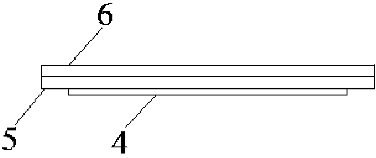
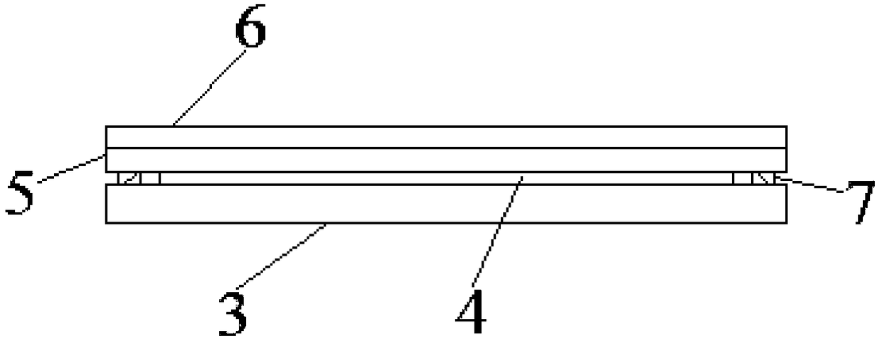
[0051] 1) if figure 2 As shown, stick the single-sided adhesive layer 4 and the single-sided adhesive layer protective film 5 together, and attach the auxiliary protective film 6 on the single-sided adhesive layer protective film 5, and then perform the first die-cutting, respectively The surface adhesive layer 4 and the single-sided adhesive layer protective fil...

Embodiment 2

[0066] In this embodiment, the thickness of the single-sided adhesive layer 4 is 0.005 mm, and the rest are the same as in Embodiment 1.

Embodiment 3

[0068] In this embodiment, the thickness of the single-sided adhesive layer 4 is 0.01 mm, and the rest are the same as in Embodiment 1.


PUM

PropertyMeasurementUnit
thicknessaaaaaaaaaa
thicknessaaaaaaaaaa
thicknessaaaaaaaaaa

Abstract

The invention relates to a die cutting method and device for a conductive cloth with an ultra-thin single-sided adhesive layer. The die cutting method sequentially comprises the steps of die cutting of the single-sided adhesive layer, die cutting of a handle and a first edge of a blue film layer, and die cutting of an outer contour of the conductive cloth; and the device comprises a first material-conveying unit, a first die-cutting unit, a first waste-discharging unit, a second material-conveying unit, a second die-cutting unit, a third material-conveying unit, a second waste-discharging unitand a third die-cutting unit which are arranged along a moving direction of a material belt in sequence. Compared with the prior art, the method and device provided by the invention eliminate a pre-processing process of the single-sided adhesive layer and a manual laminating process of the single-sided adhesive layer and a conductive cloth layer, match the processing process of the single-sided adhesive layer and a die cutting process of other layers of the conductive cloth together, have high processing precision and good product quality, facilitate positioning of the material belt among different die-cutting units, improve production efficiency and reduce production costs.

Description

technical field [0001] The invention belongs to the technical field of conductive cloth processing, and relates to a die-cutting method and device for conductive cloth with an ultra-thin single-sided adhesive layer. Background technique [0002] The conductive cloth is composed of a conductive cloth surface layer, a conductive cloth adhesive layer attached to one side of the cloth surface layer, and a conductive cloth protective film attached to the conductive cloth adhesive layer. The gap between the conductive cloth adhesive layer and the conductive cloth protective film is There is also a blue film layer as a handle, a part of the blue film layer is located between the conductive cloth adhesive layer and the conductive cloth protective film, and the other part is exposed, so that the conductive cloth protective film can be easily torn off. In the conductive cloth product used to wrap the antenna, because the cloth surface layer of the conductive cloth has lines and the su...

Claims


Application Information

Patent Timeline
Patent Type & Authority Applications(China)
IPC IPC(8): B32B37/12B32B38/00B26F1/38B26F1/44B26D7/06
CPCB26D7/06B26F1/38B26F1/44B32B37/12B32B38/00B32B38/0004
Inventor 蒋建国刘晓鹏
Owner 上海昊佰智造精密电子股份有限公司
Learn More