
Refrigeration and heating decorative plate

A decorative panel and refrigeration technology, applied in heating and ventilation control systems, heating and ventilation safety systems, heating methods, etc., can solve the problems of inconvenient disassembly, complicated construction steps, high labor costs, etc., and achieve good environmental performance and energy saving Obvious effect, good energy saving effect

Active Publication Date: 2018-10-16
深圳东盟建材实业有限公司
View PDF14 Cites 2 Cited by
  • Summary
  • Abstract
  • Description
  • Claims
  • Application Information

AI Technical Summary

Problems solved by technology

[0003] The traditional decoration floor heating system needs to make the foundation and heating device first, then fix it with cement, and then pave the decorative board. The construction steps are complicated, the disassembly and assembly are extremely inconvenient, and the labor cost is high.

Method used


Image

  • Refrigeration and heating decorative plate
  • Refrigeration and heating decorative plate
  • Refrigeration and heating decorative plate

Examples


Embodiment Construction

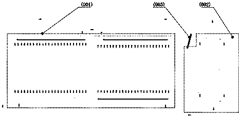
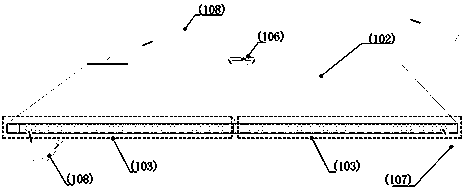
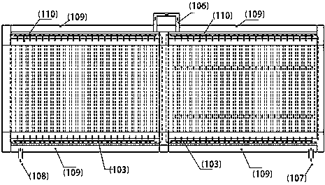
[0029] see Figure 1-6 , a cooling and heating decorative panel, including a decorative panel body ( figure 1 (001)), semiconductor modules ( Figure 4 (201)(202)), cooling and heating water tank ( figure 1 (002)), circulating water pump ( Figure 4 (208)), outlet tee module A1 ( Figure 4 (206)), return water tee module B1 ( Figure 4 (214)) and the control module ( figure 1 (003)); the decorative plate body, through the water supply pipe ( figure 2 (107)) to connect the circulating water pump ( Figure 4 (208)), through the return pipe ( figure 2 (108)) and backwater tee module B1 ( Figure 4 (214)) to connect the cooling and heating water tank ( figure 1 (002)), the circulating water pump ( Figure 4 (208)) through the outlet tee module A1 ( Figure 4 (206)) to connect the cooling and heating water tank, the semiconductor module ( Figure 4 (201)(202)) located in the cooling and heating water tank ( figure 1 (002)) inside, the semiconductor module ( Figure ...


PUM


Abstract

The invention discloses a refrigeration and heating decorative plate. The refrigeration and heating decorative plate comprises a decorative plate body, semiconductor modules, refrigeration and heatingwater tanks, a circulating water pump, a water outlet tee module, a backwater tee module and a control module. The decorative plate body is connected with the circulating water pump through a feed pipe and connected with the refrigeration and heating water tanks through a backwater pipe and the backwater tee module. The circulating water pump is connected with the refrigeration and heating watertanks through the water outlet tee module. The semiconductor electronic modules are sealed by insulation metal heat-conducting slices and arranged in the refrigeration water tank and the heating watertank. The semiconductor modules, the refrigeration and heating water tanks, the circulating water pump, the water outlet tee module and the backwater tee module are connected with the control moduleby means of a wired circuit, and the control module is located on upper cover plates of the refrigeration and heating water tanks. In different seasons, different instructions are activated, and functions are automaticlly switched, health and comfort are brought to household life, and the purpose of energy saving and emission reduction can be achieved.

Description

technical field [0001] The invention relates to the field of interior decoration, in particular to a cooling and heating decorative board. Background technique [0002] There are only a few methods that are environmentally friendly, healthy, effective, and beautiful in indoor cooling and heating devices, and very few of them do not produce a greenhouse effect on zero emissions of air, and can recycle energy. In reality, a device that can both cool and heat has dual functions. Due to cost and hardware installation conditions, it is difficult to popularize and promote it in the decoration field, and it is difficult for everyone to enjoy it. Commonly used indoor cooling and heating equipment, such as air conditioners, compressors are noisy, consume electricity, and the heat emitted by the air accelerates the greenhouse effect, and the moisture in the air is taken away, and the cold or heat is uneven, which will also cause partial health in the sub-health group. Headaches, froz...

Claims


Application Information

Patent Timeline
Patent Type & Authority Applications(China)
IPC IPC(8): E04F13/08F24F5/00F24F11/50
CPCE04F13/08E04F2290/02E04F2290/023F24F5/0042F24F11/50
Inventor 唐相平
Owner 深圳东盟建材实业有限公司
Learn More