
Vacuum pump with auxiliary exhausting mechanism

A technology of exhaust mechanism and vacuum pump, which is applied to components of pumping devices for elastic fluid, rotary piston type/swing piston type pump components, pumps, etc., which can solve the problem of limited placement space, time-consuming and laborious moving of vacuum pump Increase the occupied area of ​​the vacuum pump and other issues to achieve the effect of increasing the installation position, reducing the adjustment probability, and improving the efficiency of oil and gas separation

Inactive Publication Date: 2018-10-16
ULVAC NINGBO
View PDF0 Cites 1 Cited by
  • Summary
  • Abstract
  • Description
  • Claims
  • Application Information

AI Technical Summary

Problems solved by technology

[0005] An exhaust pipe is connected outside the exhaust port of the oil-gas separator, and the filtered air is exhausted from the exhaust pipe to the outside or collected in the gas collection container. In the actual work process, the equipment in the workshop is dense and the storage space is limited. In addition, various pipelines and lines are densely packed. Generally, there is only one exhaust port on the oil-gas separator, and the setting method is too simple. The external exhaust pipe can only be connected to the exhaust port of the oil-gas separator. Once the other end of the exhaust pipe The position changes. In order to avoid the gas transmission being affected by the folding of the exhaust pipe, the position of the vacuum pump needs to be adjusted. This requires more reserved space for the vacuum pump, which increases the occupied area of ​​the vacuum pump, and it is time-consuming and laborious to move the vacuum pump, which cannot meet the needs of the workshop. Flexible work needs

Method used


Image

  • Vacuum pump with auxiliary exhausting mechanism
  • Vacuum pump with auxiliary exhausting mechanism
  • Vacuum pump with auxiliary exhausting mechanism

Examples


Embodiment

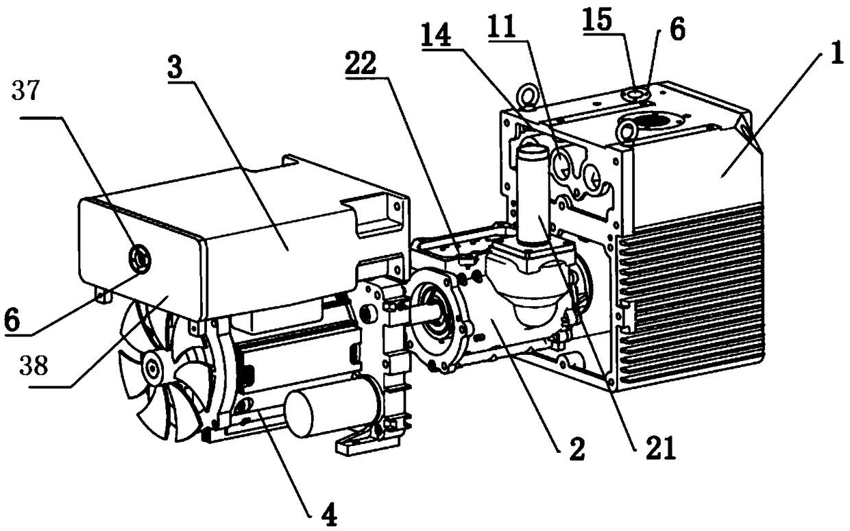
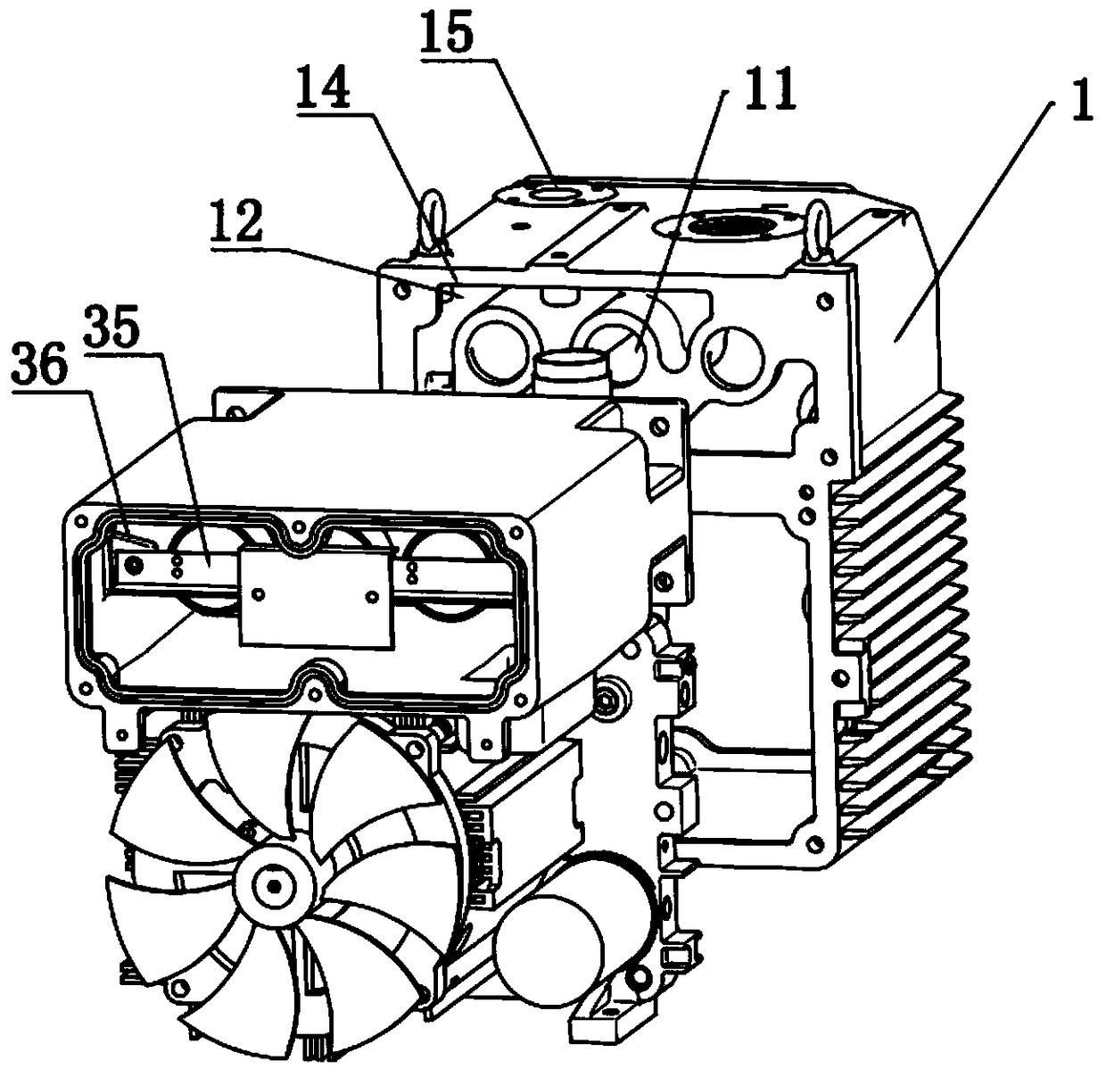
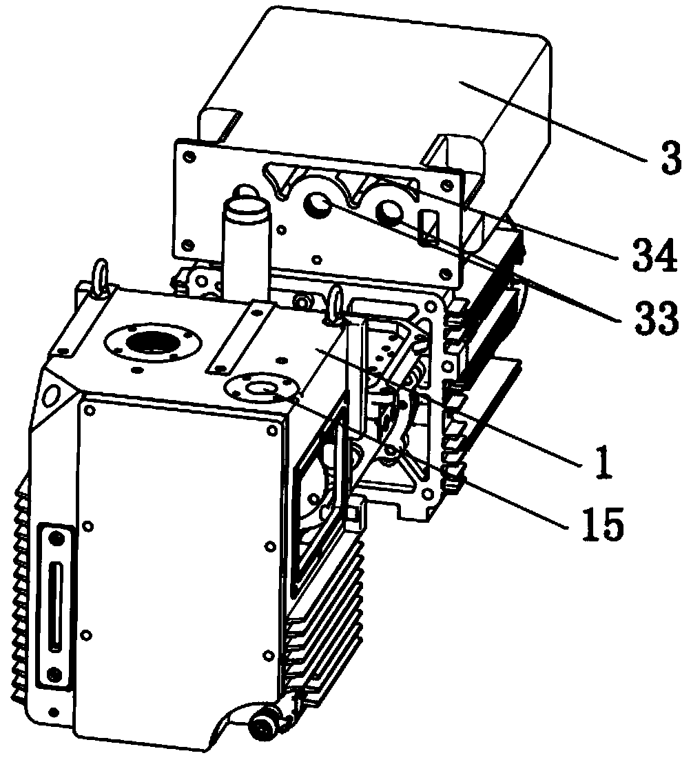
[0034] A vacuum pump with an auxiliary exhaust mechanism, refer to Figure 1-Figure 5 As shown, it includes a fuel tank 1, a pump body 2 arranged in the fuel tank 1, and an oil-gas separator 3 arranged on one side of the fuel tank 1, and a motor 4 for driving the pump body 2 is arranged on the side of the fuel tank 1, and the output shaft of the motor 4 passes through The coupling is connected to the output shaft of the inner rotor of the pump body 2, the oil-air separator 3 is arranged above the motor 4, and the two sides of the top of the pump body 2 are provided with a suction pipe 21 communicating with the inside of the pump body 2 and a first exhaust port 22. The height of the first exhaust port 22 is greater than the maximum liquid level of the fuel tank 1 . The oil-gas separator 3 is arranged on the upper surface of the motor 4 and the upper surface of the oil-gas separator 3 is flat with the upper surface of the oil tank 1 .

[0035] The oil-gas separator 3 includes an ...


PUM


Abstract

The invention relates to a vacuum pump with an auxiliary exhausting mechanism. The vacuum pump comprises an oil tank, a pump body arranged in the oil tank and an oil-gas separator disposed on one sideof the oil tank; the pump body comprises a first exhausting opening formed in the top of the pump body; the oil-gas separator comprises a shell and an exhausting filter element which is fixed into the shell; a second exhausting opening is formed in the shell; a passing opening which is in butt joint with an inlet of the exhausting filter element is formed in one side, close to the shell, of the oil tank and located above the first exhausting opening; the auxiliary exhausting mechanism which communicates with the interior of the shell is disposed on the oil tank and comprises a flow guiding wall which protrudes inwards from the inner wall of the oil tank, and an exhausting cavity is formed between the inner wall of the oil tank and the flow guiding wall; and a third exhausting opening which communicates with the exhausting cavity is formed in the outer wall of the oil tank. The vacuum pump is good in oil-gas separation effect, and the mounting position selectivity of externally-connected exhausting pipes is diversified.

Description

technical field [0001] The invention relates to the field of vacuum pumps, more specifically, it relates to a vacuum pump with an auxiliary exhaust mechanism. Background technique [0002] The vacuum pump is a rotary variable-volume gas delivery pump, which vacuums the pumped containers by pumping air into them. It is widely used in pigment chemical industry, brick and tile machinery, low temperature equipment, papermaking machinery, pharmaceutical chemical industry, and food machinery. , Industrial electric furnace, electronics industry, vacuum equipment, chemical fertilizer, metallurgy, petroleum, mining, foundation treatment and other fields. [0003] A vacuum pump generally includes a fuel tank, a pump body set in the fuel tank and a motor driving the pump body. The pump body is equipped with a stator, a rotor and a rotary vane. The output shaft of the motor and the output shaft of the rotor are connected by a coupling. The principle of the vacuum pump is : When the rot...

Claims


Application Information

Patent Timeline
IPC IPC(8): F04C25/02F04C29/00F04C29/12
CPCF04C25/02F04C29/00F04C29/0092F04C29/12
Inventor 李柯迪张达吴青云
Owner ULVAC NINGBO
Learn More