High-efficiency energy-saving self-suction centrifugal pump

A self-priming centrifugal pump, high-efficiency and energy-saving technology, applied in the field of centrifugal pumps, can solve the problems of low pump efficiency, increased clearance between impeller and pump body, no more than 50%, etc., and achieves convenient maintenance and self-priming performance. Good, wide range of effects

Pending Publication Date: 2018-10-16
上海瑞晨环保科技股份有限公司
View PDF0 Cites 0 Cited by
  • Summary
  • Abstract
  • Description
  • Claims
  • Application Information

AI Technical Summary

Problems solved by technology

[0004] (1) Sealless self-controlled self-priming pumps have the advantages of reliable operation and less maintenance, but the disadvantage is low efficiency, because whether it is an internal mixing type or an external mixing type, the structure and return flow of the gas-water separation chamber determine the product performance. In order to ensure the self-priming performance and self-priming time of the product, a large return flow is generally designed to make the volume ratio of the pump low, and because of the structure of the air-water separation chamber, the velocity inside the impeller cannot be effectively converted into pressure energy, but accompanied by Shock, mutation diffusion or shrinkage loss, so the pump efficiency is low, according to the statistics, the actual operating efficiency of the general self-priming pump site is not more than 50%, resulting in a lot of waste of energy consumption, which does not meet the national energy conservation and environmental protection requirements, and The impeller of the self-priming pump cannot be cut, and the flow pressure of each pump is constant after the design is completed. After the impeller is cut, the gap between the impeller and the pump body will increase, and the gas-water mixture cannot be discharged quickly, which will affect the self-priming performance of the pump;
[0005] (2) Long-axis deep well pump, this structure pump adopts the space guide vane structure, the efficiency is relatively high, but the failure rate is also high, because the pump structure is difficult to lift and maintenance is cumbersome;
[0006] (3) Centrifugal pumps are equipped with vacuum pumps, bottom valves or vacuum water diversion devices. Although the problem of low efficiency is solved by the use of vacuum pumps, they must be vacuumed every time they are started. The operation is cumbersome, and the failure rate of the two pumps is high, especially in some In the liquid flow of impurities, there are high requirements for the sealing of ordinary centrifugal pumps, and water cannot be absorbed normally if there is a slight air leakage; with a bottom valve and a vacuum water diversion device, the hydraulic loss is large, which reduces the operating efficiency of the pump and cannot be used for suction. In the case of a large upper height, it cannot be applied to the medium containing impurities
[0007] Although the equipment with the above structures has certain advantages, they cannot achieve the balance of efficiency, self-priming performance, hydraulic performance and operational reliability.

Method used


Image

  • High-efficiency energy-saving self-suction centrifugal pump
  • High-efficiency energy-saving self-suction centrifugal pump
  • High-efficiency energy-saving self-suction centrifugal pump

Examples


Embodiment Construction

[0044] The present invention will be further described below in combination with specific embodiments. It should be understood that these examples are only used to illustrate the present invention and are not intended to limit the scope of the present invention. In addition, it should be understood that after reading the teachings of the present invention, those skilled in the art can make various changes or modifications to the present invention, and these equivalent forms also fall within the scope defined by the appended claims of the present application.

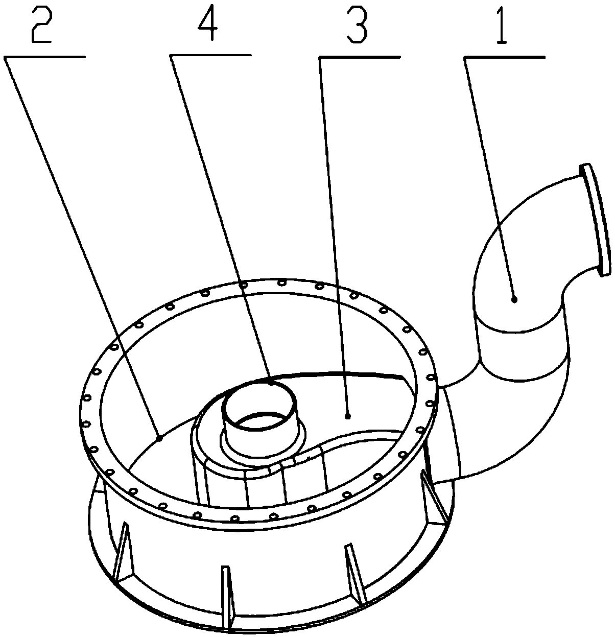
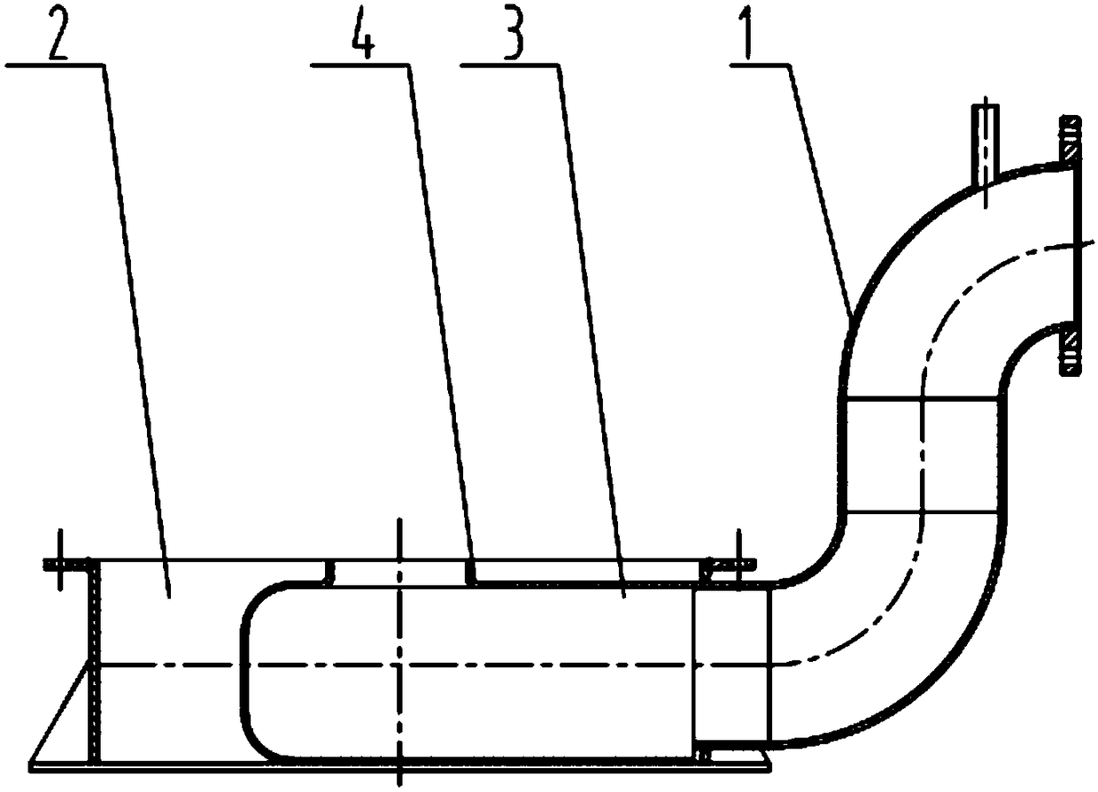
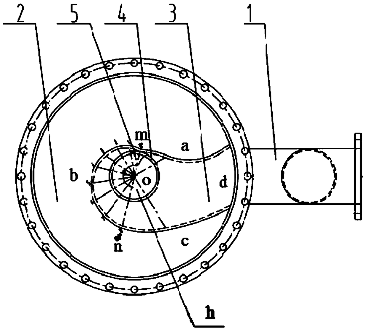
[0045] High-efficiency energy-saving self-priming centrifugal pump, including water inlet pipe 1, water storage chamber 2 and impeller, such as figure 1 with 2 As shown, the water storage chamber 2 is provided with a water absorption chamber 3, the water absorption chamber 3 is a hollow structure, surrounded by an upper bottom plate, a lower bottom plate and side plates perpendicular to the two, and a through hole is op...


PUM


Abstract

The invention relates to a high-efficiency energy-saving self-suction centrifugal pump. The high-efficiency energy-saving self-suction centrifugal pump comprises a water inlet pipe, a water storage chamber and an impeller. The water storage chamber is internally provided with a water suction chamber. The water suction chamber is defined by an upper bottom plate, a lower bottom plate and side plates perpendicular to the upper bottom plate and the lower bottom plate. A hole h of the upper bottom plate upwards extends along a hole wall to form a water outlet pipe, and the water outlet pipe is connected with the impeller. The edge line of a cross section of the side plates is formed by sequentially connecting a curve a, a helical line b, a curve c and a line d, the curve a and the curve c arein smooth transition with the helical line b, the side plate where the line d is located is provided with a hole k, and the hole k is connected with a water inlet pipe. The intersection point of the helical line b and the curve a is m, the intersection point of the helical line b and the curve c is n, m, n and a circle center o of the hole h are located on the same straight line, the length of a line segment between a point on the helical line b and o is R, the included angle between a line segment between the point on the helical line b and o and the line segment between m and o is theta, andR=D0 (A+Btheta/C). The high-efficiency energy-saving self-suction centrifugal pump achieves efficiency, the self-suction performance, the hydraulic performance and the running reliability performanceand can be used and popularized.

Description

technical field [0001] The invention belongs to the field of centrifugal pumps and relates to a high-efficiency energy-saving self-priming centrifugal pump. Background technique [0002] The self-priming pump is a centrifugal pump with a special structure. It only needs to be started for the first time to fill water, and then it can be started directly. It has the advantages of convenient use, reliable operation and convenient remote centralized control. But the disadvantage is low efficiency. The existing self-priming pumps are divided into two structures: internal mixing type and external mixing type. The internal mixing type is for the liquid flow back to the impeller inlet. The self-priming pump with this structure has relatively high efficiency, and the external mixing type is for the liquid flow back to the impeller Outlet, the efficiency is relatively low, but the self-priming time is short, but whether it is an external-mixing or internal-mixing self-priming pump, i...

Claims


Application Information

Patent Timeline
Patent Type & Authority Applications(China)
IPC IPC(8): F04D1/00F04D9/02F04D29/44
CPCF04D1/00F04D9/02F04D29/445
Inventor 赵鹏举陆银华陈招锋程原
Owner 上海瑞晨环保科技股份有限公司
Why Eureka
Try Eureka