Liftable spinning machine

A textile machine, bottom-fixed technology, applied in mechanical equipment, supporting machines, engine bases, etc., can solve problems such as reducing textile work efficiency, textile machine adjustment, discomfort, etc., to facilitate movement, improve efficiency, and improve balance performance. Effect

Inactive Publication Date: 2018-10-16
湖州南浔富龙纺织有限公司
7 Cites 4 Cited by

AI-Extracted Technical Summary

Problems solved by technology

[0003] Textile fabrics need to be processed by textile machines. When the existing textile machines are in use, the height of the textile machines cannot be adjusted a...

Method used

In sum, this liftable textile machine, by arranging the second motor 5, drives the second motor 5, can drive moving piece 9 to adjust up and down on threaded rod 8, before textile machine is used, the staff can The height of the textile machine is adjusted according to the height of the individual. When the textile machine is in use, the height of the textile machine is adjusted. The staff can adjust the height of the textile machine according to their own needs. It is more comfortable to use the textile machine, which greatly improves the textile quality. work efficiency, by setting the first anti-slip pad 13 and the second anti-slip pad 16, the anti-slip pad can increase the friction with the ground, play a fixed role on the textile machine, greatly improve the stability of the device, improve the balance per...

Abstract

The invention provides a liftable spinning machine, and relates to the field of spinning equipment. The liftable spinning machine comprises a worktable; a damping device is fixedly mounted at the bottom of the worktable; a support column is fixedly mounted at the bottom of the damping device; a groove is formed in the support column; a support base is arranged on the lower side of the support column; a first antiskid pad is fixedly mounted at the bottom of the support base; a movable base is fixedly mounted on one side of the support base; and a second antiskid pad is arranged at the bottom ofthe movable base. The liftable spinning machine is provided with a second motor; the second motor is driven to drive a movable block to adjust up and down on a thread rod; before the spinning machineis used, workers can adjust the height of the spinning machine according to personal heights; and when the spinning machine is used, the height of the spinning machine is adjusted, and the workers can adjust the height of the spinning machine according to self demands, so that the spinning machine is used more comfortably, and the spinning efficiency is greatly improved.

Application Domain

Non-rotating vibration suppressionEngine beds

Technology Topic

Industrial engineering

Image

  • Liftable spinning machine
  • Liftable spinning machine
  • Liftable spinning machine

Examples

  • Experimental program(1)

Example Embodiment

[0022] The technical solutions in the embodiments of the present invention will be clearly and completely described below with reference to the accompanying drawings in the embodiments of the present invention.
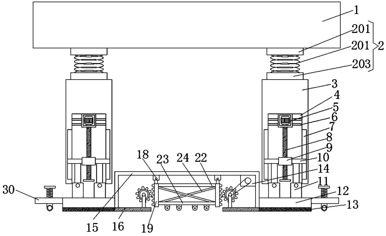
[0023] Embodiments of the present invention provide a liftable textile machine, such as Figure 1-3 As shown in the figure, including the workbench 1, the bottom of the workbench 1 is fixedly installed with a damping device 2. By setting the damping device 2, the vibration generated by the textile machine can be absorbed, which greatly improves the stability of the textile machine and greatly prolongs the The service life of the textile machine, the damping device 2 includes an upper fixing plate 201, the top of the upper fixing plate 201 is fixedly installed with the bottom of the worktable 1, and the lower side of the upper fixing A shock-absorbing spring 202 is fixedly installed at the bottom. By setting the shock-absorbing spring 202, the spring acts as a shock absorber, which can greatly improve the efficiency of shock absorption. One end of the shock-absorbing spring 202 is fixedly installed with the top of the lower fixing plate 203. The bottom of the lower fixing plate 203 is fixedly installed with the top of the support column 3, the bottom of the shock absorber 2 is fixedly installed with the support column 3, the inside of the support column 3 is provided with a groove 4, and the top of the groove 4 is fixedly installed with a second motor 5. By setting the second motor 5 and driving the second motor 5, the moving block 9 can be adjusted up and down on the threaded rod 8. Before the textile machine is used, the staff can adjust the height of the textile machine according to the height of the individual. When in use, the height of the textile machine is adjusted, and the staff can adjust the height of the textile machine according to their own needs, which makes the use of the textile machine more comfortable and greatly improves the work efficiency of textile work. Both sides of the second motor 5 are fixed A bracket 6 is installed. By setting the bracket 6, the second motor 5 can be fixed, so as to avoid the situation that the second motor 5 is shaking during use. The groove 4 is provided with a threaded rod 8 inside the second motor. The rotating shaft of 5 is connected with the threaded rod 8 in a transmission connection, the surface of the threaded rod 8 is sleeved with a moving block 9, the two sides of the moving block 9 are fixedly installed with sliding rods 10, and the two sides of the inner wall of the support column 3 are provided with sliding grooves 7, By arranging the sliding slot 7, it is convenient for the sliding rod 10 to move up and down on the threaded rod. The sliding slot 7 is slidably connected to the sliding rod 10 through the sliding block in the sliding slot 7. The bottom of the sliding rod 10 is fixedly installed with the first electric telescopic rod 11. The first electric telescopic rod 11 can play the role of supporting and telescopic. The bottom of the first electric telescopic rod 11 is fixedly installed with the top of the support seat 12, the lower side of the support column 3 is provided with a support seat 12, and the bottom of the support seat 12 is fixed The first anti-skid pad 13 is installed. By setting the first anti-skid pad 13, the anti-skid pad can increase the friction with the ground, play a fixed role on the textile machine, greatly improve the stability of the device, and improve the balance performance. The effect is better, avoiding the situation of the textile machine moving during use, the movable base 15 is fixedly installed on one side of the support base 12, and the second electric telescopic rod 18 is fixedly installed on both sides of the bottom of the movable base 15. The two electric telescopic rods 18 can fix the first support rod 25 and the second support rod 19. One end of the second electric telescopic rod 18 is respectively fixed with the first support rod 25 and the second support rod 19. A first fixing rod 22 is arranged between a support rod 25 and the second support rod 19 , a second fixing rod 23 is arranged on the lower side of the first fixing rod 22 , the first fixing rod 22 and the second fixing rod A diagonal rod 24 is arranged between the 23. By setting the diagonal rod 24, it plays the role of fixed support and improves the stability of the roller 21. The bottom of the second fixed rod 23 is fixedly installed with a supporting leg 20, and the number of supporting legs 20 is quite large. Among the four, the bottom of the support leg 20 is fixedly installed with a roller 21. By setting the roller 21, the movement of the textile machine is facilitated, and the work efficiency is greatly improved. There are teeth 26, the first support rod 25 and the first gear 29 are meshed by the teeth 26, the bottom of the mobile base 15 is provided with a second anti-skid pad 16, and by setting the second anti-skid pad 16, the anti-skid pad can increase the friction with the ground , plays a fixed role on the textile machine, greatly improves the stability of the device, improves the balance performance, and the effect is better in use, avoiding the situation of the textile machine moving during use, moving the two sides of the top of the base 15 A support column 28 is fixedly installed, one end of the support column 28 is provided with a rotating shaft 27, the interior of the mobile base 15 is provided with a first motor 14, and the rotating shaft of the first motor 14 is connected with the rotating shaft 27 in a driving manner, and one side of the support column 3 is respectively provided with There are a first gear 29 and a second gear 17. By setting the first gear 29 and the second gear 17 to drive the first motor 14, the roller 21 can be extended and retracted. In order to improve the stability of the textile machine, one side of the support base 12 is provided with a support device 30, the support device 30 includes a bump 303, an adjustment bolt 302 is arranged on the upper side of the bump 303, and an adjustment handle is fixedly installed on the top of the adjustment bolt 302. 301, one end of the adjusting bolt 302 extends to the bottom of the bump 303, and the bottom of the adjusting bolt 302 is fixedly installed with a moving wheel 304. By setting the moving wheel 304, it not only plays a supporting role, but also facilitates the movement of the textile machine.
[0024]To sum up, the liftable textile machine, by setting the second motor 5 and driving the second motor 5, can drive the moving block 9 to adjust up and down on the threaded rod 8. Before the textile machine is used, the staff can The height of the textile machine can be adjusted by height. When the textile machine is in use, the height of the textile machine can be adjusted. The staff can adjust the height of the textile machine according to their own needs. It is more comfortable to use the textile machine and greatly improves the work efficiency of textile work. , By setting the first anti-skid pad 13 and the second anti-skid pad 16, the anti-skid pad can increase the friction with the ground, play a fixed role on the textile machine, greatly improve the stability of the device, and improve the balance performance. The effect is better, avoiding the situation of the textile machine moving during use. By setting the roller 21, the movement of the textile machine is convenient, and the work efficiency is greatly improved. By setting the first gear 29 and the second gear 17, it drives the first The motor 14 and the roller 21 can be extended and retracted, and the roller 21 can be retracted into the moving base 15 when not moving, which greatly improves the stability of the textile machine. The stability of the textile machine is improved, and the service life of the textile machine is greatly prolonged. By setting the bracket 6, the second motor 5 can be fixed, and the second motor 5 can be prevented from shaking during use.
[0025] Although embodiments of the present invention have been shown and described, it will be understood by those skilled in the art that various changes, modifications, and substitutions can be made in these embodiments without departing from the principle and spirit of the invention and modifications, the scope of the invention is defined by the appended claims and their equivalents.

PUM

no PUM

Description & Claims & Application Information

We can also present the details of the Description, Claims and Application information to help users get a comprehensive understanding of the technical details of the patent, such as background art, summary of invention, brief description of drawings, description of embodiments, and other original content. On the other hand, users can also determine the specific scope of protection of the technology through the list of claims; as well as understand the changes in the life cycle of the technology with the presentation of the patent timeline. Login to view more.

Similar technology patents

Automatic device for welding and detecting lithium battery

ActiveCN103904367AShorten the running distanceImprove work efficiency
Owner:DONGGUAN HONBRO LI BATTERY EQUIP TECH

Vacuum cleaner

InactiveCN103356140Aprevent liftingImprove work efficiency
Owner:SUZHOU HAAN TECH +1

Classification and recommendation of technical efficacy words

  • Improve stability
  • Improve work efficiency

Cooperation service platform facing different source data

InactiveCN101174957AImprove management level and qualityImprove work efficiency
Owner:NANJING UNIV OF FINANCE & ECONOMICS

Screw drilling tool, vertical drilling tool testing method and well inclination simulation testing equipment

InactiveCN111594144AReduced height requirementsImprove work efficiency
Owner:DEZHOU UNITED GASOLINEEUM MACHINERY

Method for intelligent automatic identification of transmission circuit parts

Owner:INFORMATION COMM COMPANY STATE GRID SHANDONG ELECTRIC POWER +2

Keyboard spill-proofing mechanism

ActiveUS7030330B2minimize manufacturing costimprove work efficiency
Owner:LITE ON SINGAPORE PTE LTD
Why Eureka
Try Eureka