Emergency processing method and device for falling of sliding valve gate plate through catalyst

An emergency treatment and catalyst technology, applied in valve devices, sliding valves, valve details, etc., can solve problems such as large profit loss, safety problems, long maintenance time, etc., and achieve the effect of huge benefits and simple structure.

Pending Publication Date: 2018-10-16
YUEYANG CHANGLING EQUIP RES INST
View PDF7 Cites 1 Cited by
  • Summary
  • Abstract
  • Description
  • Claims
  • Application Information

AI Technical Summary

Problems solved by technology

The disadvantages of downtime maintenance are not only the loss of benefits, but also: ①Long maintenance time, delaying production progress, slow cooling of equipment during shutdown, and slow rise of equipment temperature when starting up; ②Once shutdown and restart, many unexpected events will occur equipment and production problems; ③ It may not be possible to start successfully at the first time; ④ There are many safety problems when starting and stopping

Method used


Image

  • Emergency processing method and device for falling of sliding valve gate plate through catalyst

Examples


Embodiment 1

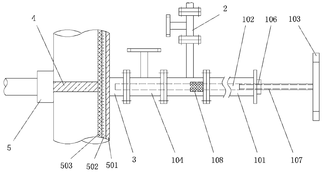
[0019] like figure 1 As shown in the figure, an emergency treatment device for catalyst spool valve gate falling off includes a gate ejection device and a purge bypass 2. The gate ejection device includes a cylinder 101, a lead screw ejector rod 102, and a valve handle 103. One end of the barrel 101 is connected to the flange nipple 3 through a gate valve 104, and the other end is provided with a threaded hole 106. The screw jack 102 passes through the threaded hole 106, and one end penetrates the barrel 101 and extends into the flange nipple. Section 3, the other end is connected to the valve handle 103, and the end connected to the valve handle 103 is provided with a screw thread 107 that matches the threaded hole 106. Rotating the valve handle 103 can make the screw rod 102 move in the cylinder body 101, and the slide valve gate can be moved. When the plate 4 pushes back to 100% opening, it can also withdraw from the internal channel of the slide valve, without hindering th...

Embodiment 2

[0022] A method for disposing of a damaged slide valve using the emergency treatment device for the gate plate falling off of the catalyst slide valve described in Example 1. The valve body 5 of the slide valve includes three layers from the outside to the inside: a shell made of metal material 16Mn and a wall thickness of 20mm Body 501; thermal insulation lining 502 with a thickness of 80mm; silicon cross-network 503 with a thickness of 20mm, and a medium temperature of 650°C, including the following steps:

[0023] S1: Install the flange nipple 3 at the precise position on the back of the spool valve 5 and perform pressure drilling. The effective length of the drilling knife is greater than 140mm, and the length calculation method is 20+80+20+6 (thickness of the bottom of the knife) + 14 ( The invalid length of the tip or drill tip), the material is a high-temperature alloy knife, and the hardness is higher than that of silicon cross-network 503;

[0024] S2: Install the val...


PUM


Abstract

The invention relates to an emergency processing method for falling of a sliding valve gate plate through a catalyst. The method comprises the following steps that S1, a flange short-section hot-tapping hole is formed in the accurate portion of the back side of a sliding valve; S2, a gate plate jacking-back device and a blowing device are installed on a flange short-section, specifically, the gateplate jacking-back device comprises a lead screw ejector rod; and S3, the lead screw ejector rod penetrates through the formed hole, the sliding valve gate plate can be further pushed to open the sliding valve, a broken valve rod on the other side of the sliding valve can still the sliding valve gate plate to close to the sliding valve, the sliding valve control effect recovers, and blowing is carried out every time the sliding valve gate plate is opened or closed. The invention further discloses a device for the method. Online operation can be achieved, shutdown is not needed, benefits are great, the structure is simple, and safety and reliability are achieved.

Description

technical field [0001] The invention relates to a method and a device for emergency treatment of catalyst slide valve shutter falling off, in particular to an on-line treatment method for a non-stop production line. Background technique [0002] Catalytic devices are the leading efficiency-creating units in the petroleum and chemical industries. The catalytic device has many sensitive control slide valves. Due to the long-term high-temperature wear of the catalyst during the production process, these slide valves may break the valve stem and the valve plate cannot be opened and closed freely. Shutdown for inspection and repair; if it is serious, it must be urgently shut down for emergency repairs, resulting in tens of millions of benefit losses and a huge impact. [0003] For a long time, the separation of the valve stem and the valve plate has occurred in various petroleum and chemical enterprises, accounting for about 10% to 15% of the total accidents. With the prolongat...

Claims


Application Information

Patent Timeline
Patent Type & Authority Applications(China)
IPC IPC(8): F16K3/02F16K3/314F16K41/02
CPCF16K3/02F16K3/0227F16K3/314
Inventor 刘玉莫建伟张常青陈业楠
Owner YUEYANG CHANGLING EQUIP RES INST
Why Eureka
Try Eureka