Non-contact type cable voltage measuring sensor

A voltage measurement, non-contact technology, applied in the field of sensors, can solve the problems of complex insulation structure, high-frequency oscillation of ferromagnetic resonance, inability to meet, etc., to ensure safety and convenience, eliminate magnetic saturation, and reduce insulation difficulty. Effect

Pending Publication Date: 2018-10-16
BEIJING TFLYING TRANSDUCER TECH CO LTD
View PDF9 Cites 3 Cited by
  • Summary
  • Abstract
  • Description
  • Claims
  • Application Information

AI Technical Summary

Problems solved by technology

Restricted by its working principle, the electromagnetic voltage transformer can no longer meet the requirements of large capacity and high voltage level of the current smart grid in some aspects of performance. The existing problems include: the high voltage side must have a high dielectric strength, so that the insulation structure More complex, bulky, and costly; there are problems such as small dynamic range, ferromagnetic resonance, and core saturation
Capacitive voltage transformers have poor transient response due to internal energy storage components such as coupling capacitors, intermediate transformers, and compensation reactors, and under high-frequency overvoltages, high-frequency vibrations caused by ferromagnetic resonance are prone to occur on the low-voltage side. oscillation, which threatens the safe operation of the equipment

Method used


Image

  • Non-contact type cable voltage measuring sensor
  • Non-contact type cable voltage measuring sensor
  • Non-contact type cable voltage measuring sensor

Examples


no. 1 example

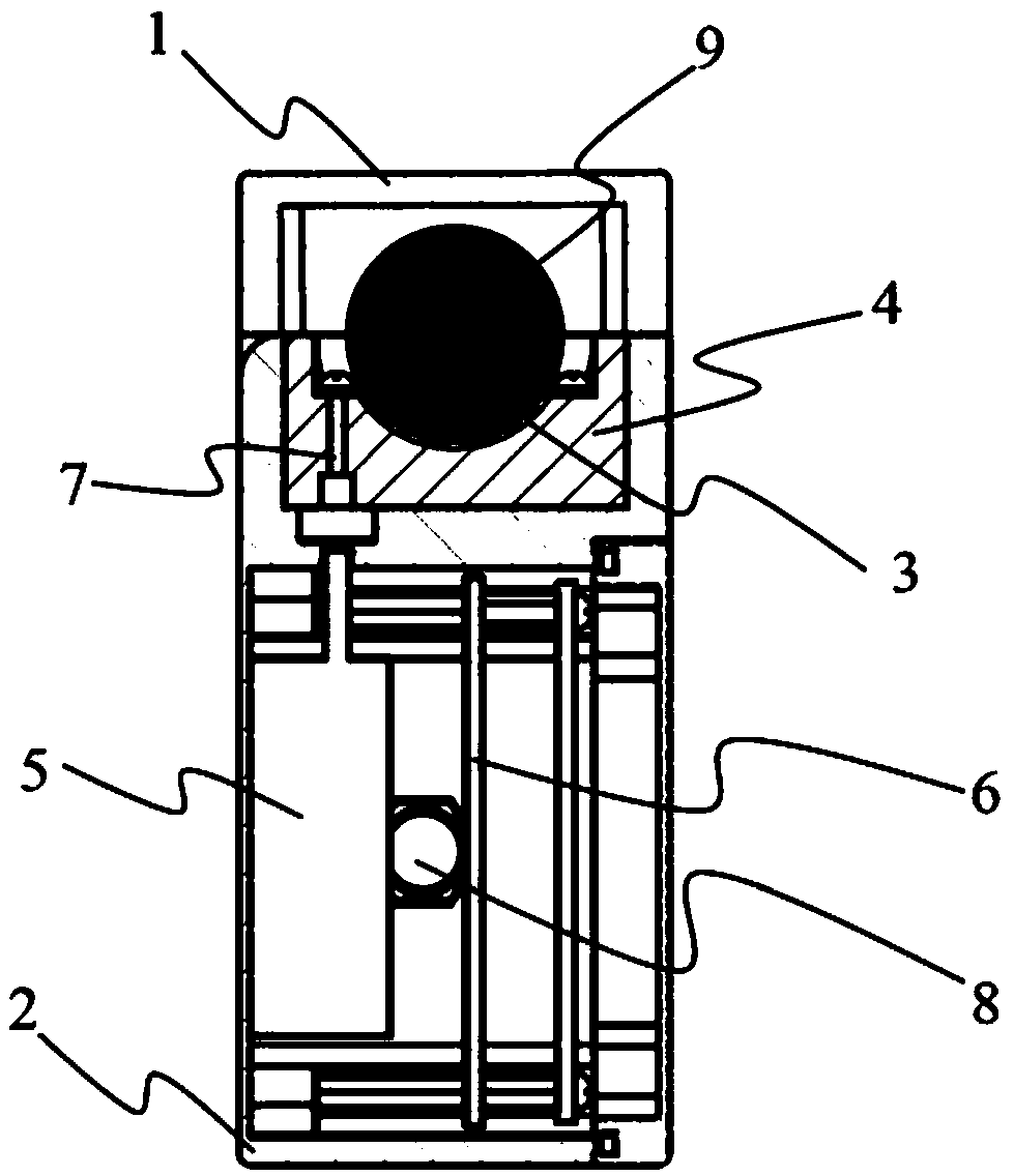
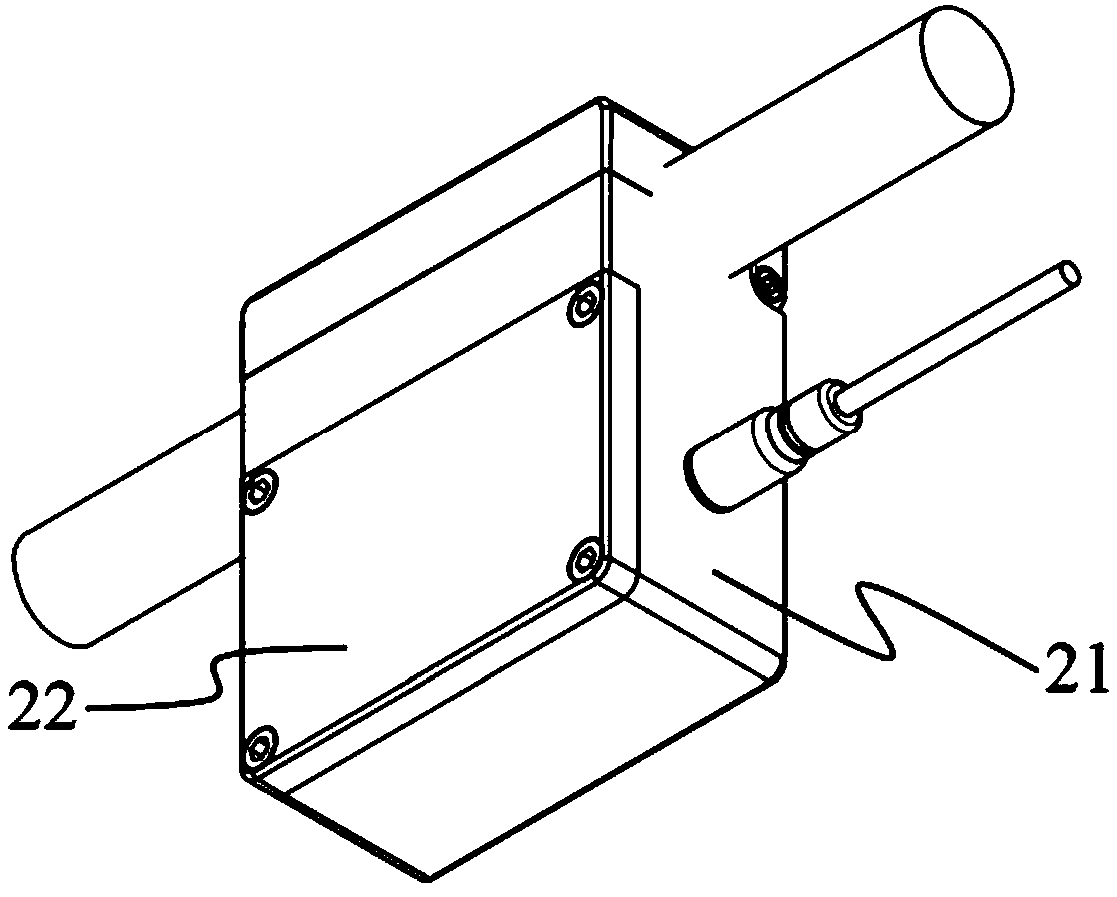
[0055] In the first exemplary embodiment of the present invention, a non-contact cable voltage measurement sensor is provided. figure 1 It is a schematic diagram of the cross-sectional structure of the non-contact cable voltage measurement sensor perpendicular to the cable axis direction according to the first embodiment of the present invention. Such as figure 1 As shown, the non-contact cable voltage measurement sensor of the present invention includes: a shielding cover 1, a housing 2, a detection electrode 3, an insulator 4, an electric field measurement module 5, a signal demodulation and communication circuit 6, an electrode wire 7 and an aviation Insert the female seat 8.

[0056] The shielding cover 1 is connected with the housing 2 to form a cavity structure. The cable 9 to be tested is inserted through the cavity structure. The shielding cover 1 can shield the influence of the external electric field on the cable to be tested 9 and make the voltage measurement accurate ...

no. 2 example

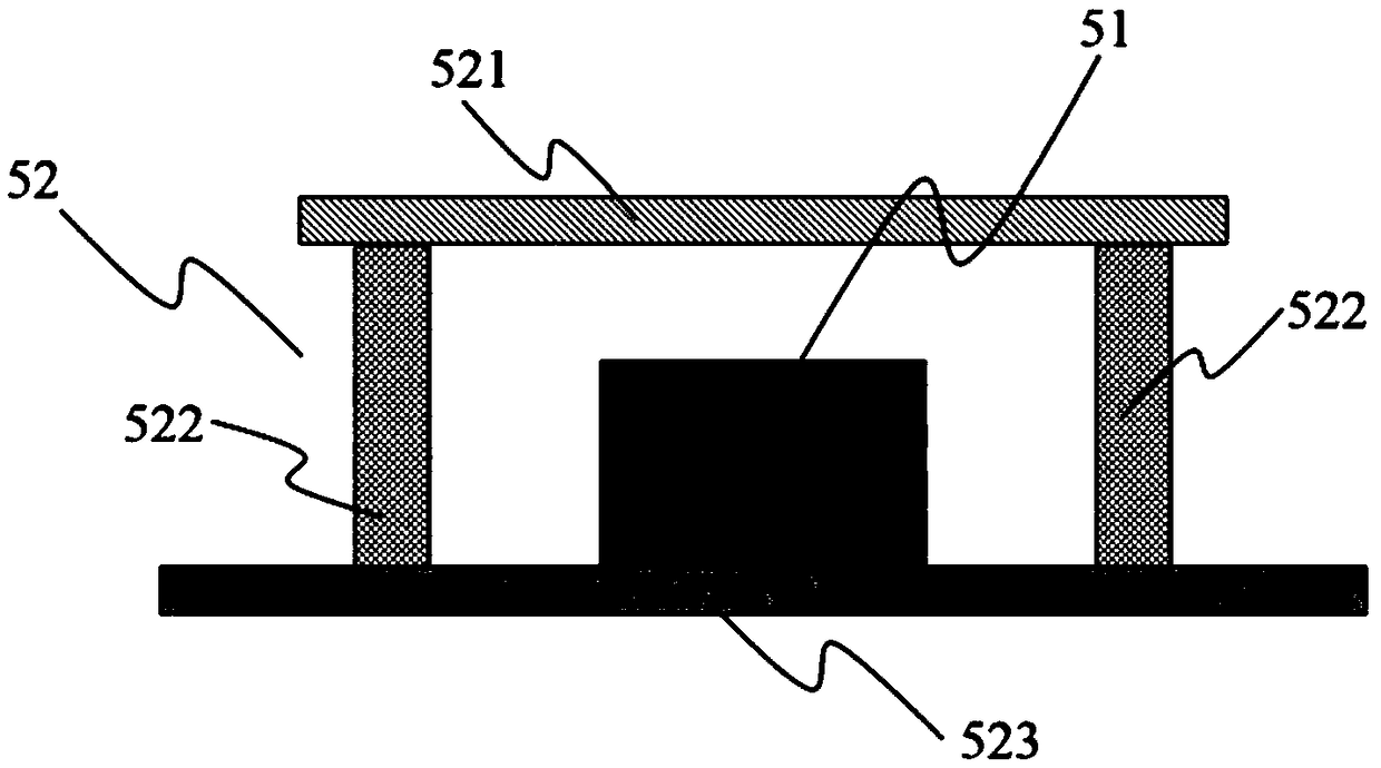
[0070] In the second exemplary embodiment of the present invention, a non-contact cable voltage measurement sensor is provided. Figure 5 It is a schematic cross-sectional view of a part of the structure perpendicular to the cable axis direction of the second embodiment of the present invention. Such as Figure 5 As shown, compared with the non-contact cable voltage measurement sensor of the first embodiment, the difference of the non-contact cable voltage measurement sensor of this embodiment is:

[0071] An insulating layer 10 is provided on the upper surface of the detection electrode 3 to completely cover the cable 9 under test. When the cable 9 under test is circular, the outer shape of the insulating layer 10 is circular, and its inner diameter is greater than or equal to the outer diameter of the cable 9 under test. Of course, the insulating layer 10 can also be partially connected to the detection electrode 3, and the other part is connected to the inside of the rotating ...

no. 3 example

[0075] In the third exemplary embodiment of the present invention, a non-contact cable voltage measurement sensor group is provided. Image 6 It is a schematic cross-sectional view of a part of the structure perpendicular to the cable axis direction of the third embodiment of the present invention. Such as Image 6 As shown, the non-contact cable voltage measurement sensor group of the present invention includes three non-contact cable voltage measurement sensors, and each non-contact cable voltage measurement sensor is the same as the non-contact cable voltage measurement in the second embodiment. The structure of the sensors is the same, but the thickness of the insulating layer 10 in each non-contact cable voltage measurement sensor is not consistent.

[0076] Using multiple non-contact cable voltage measurement sensors to measure the voltage of high-voltage cables can eliminate common mode interference noise and further improve measurement accuracy.


PUM


Abstract

The invention provides a non-contact type cable voltage measuring sensor, comprising: a housing, an insulating member, a detecting electrode, an electric field measuring module, a signal demodulationand communication circuit and an aviation socket, wherein the insulating member is fixed at a groove in the housing; the detecting electrode is fixed on the upper surface of the insulating member, istightly connected with the insulating member, and is used for generating induced charge; the electric field measuring module is fixed inside the housing, is electrically connected with the detecting electrode through an electrode lead, and is used for measuring the electric field strength; the signal demodulation and communication circuit is fixed inside the housing, is electrically connected withthe electric field measuring module through a wire, and is used for analyzing and calculating electric field signals and converting the same into voltage signals; the aviation socket is mounted on the side wall of the housing, is electrically connected with the signal demodulation and communication circuit through wire, and is used for providing a power supply for the electric field measuring module and the signal demodulation and communication circuit and providing an interface for signal output.

Description

Technical field [0001] The invention relates to the technical field of sensors, in particular to a non-contact cable voltage measurement sensor. Background technique [0002] At present, the sensor used for cable voltage measurement in the power system is a voltage transformer. Its main function is to transform the high voltage (primary side) of the cable into a low voltage suitable for the work of relay protection devices and measuring instruments. The high-voltage side is electrically isolated from the low-voltage side. Voltage transformers used in power systems mainly include electromagnetic voltage transformers (Potential Transformer, PT) and capacitive voltage transformers (Capacitive Voltage Transformer, CVT). The electromagnetic voltage transformer is restricted by its working principle, and in some performance aspects, it can no longer meet the requirements of the current smart grid with large capacity and high voltage level. Its problems include: the high voltage side m...

Claims


Application Information

Patent Timeline
Patent Type & Authority Applications(China)
IPC IPC(8): G01R19/00
CPCG01R19/00
Inventor 杨鹏飞闻小龙彭春荣夏善红
Owner BEIJING TFLYING TRANSDUCER TECH CO LTD
Why Eureka
Try Eureka