
Micro-power isolated power source for M-BUS power supply and control method thereof

An isolated power supply and micro-power technology, which is applied in control/regulation systems, output power conversion devices, DC power input conversion to DC power output, etc., can solve problems such as inability to achieve isolated output, poor signal anti-interference ability, etc., to achieve The calculation and realization method is simple and feasible, the effect of high and low temperature performance is excellent, and the reliability is high

Pending Publication Date: 2018-10-16
MORNSUN GUANGZHOU SCI & TECH
View PDF6 Cites 3 Cited by
  • Summary
  • Abstract
  • Description
  • Claims
  • Application Information

AI Technical Summary

Problems solved by technology

[0006] In view of this, the present invention proposes a micro-power isolated power supply for M-BUS bus power supply, which can solve the existing deficiencies such as the inability to achieve isolated output and poor signal anti-interference ability in the prior art. At the same time, the present invention also provides a The control method corresponding to the micro-power isolated power supply is the second technical problem to be solved by the present invention

Method used


Image

  • Micro-power isolated power source for M-BUS power supply and control method thereof
  • Micro-power isolated power source for M-BUS power supply and control method thereof
  • Micro-power isolated power source for M-BUS power supply and control method thereof

Examples


Embodiment Construction

[0027] In order to make the present invention clearer, the present invention will be further described in detail below in conjunction with the accompanying drawings and embodiments. It should be understood that the specific embodiments described here are only used to explain the present invention, not to limit the present invention.

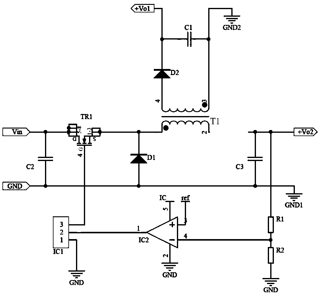
[0028] image 3 It is the schematic circuit diagram of the application of the present invention, Figure 4 It is the voltage and current sequence diagram of the application circuit of the present invention, and the circuit composition of the present embodiment is as follows:

[0029] Power devices: MOS tube TR1, capacitor C2, capacitor C3, diode D1, transformer T1: primary winding, secondary winding;

[0030] Filter circuit: diode D2, capacitor C1;

[0031] Sampling circuit: resistor R1, resistor R2;

[0032] Comparison control circuit: comparison amplifier IC2, control chip IC1.

[0033] The complete connection relationship of this embodime...


PUM


Abstract

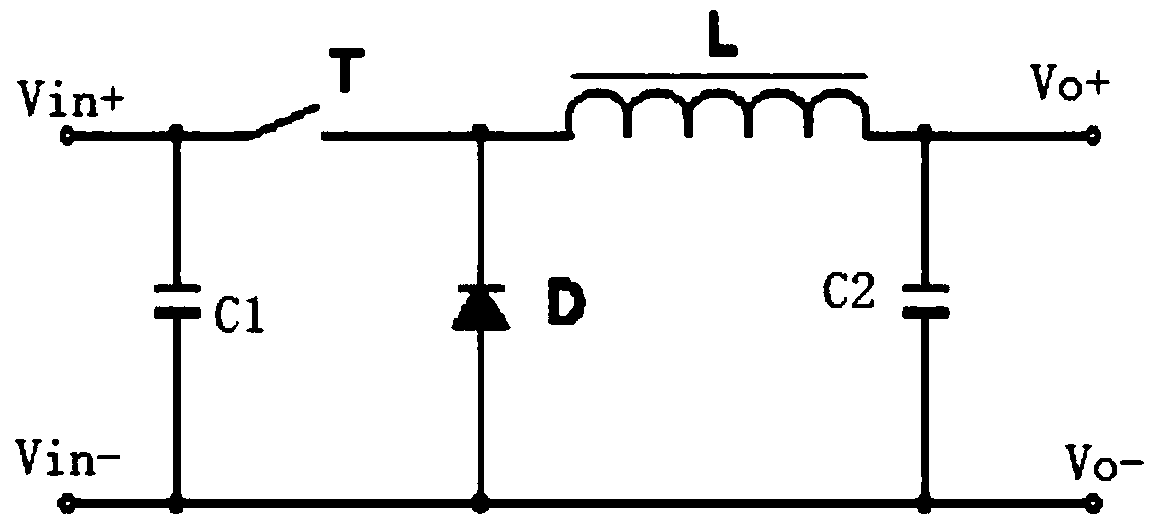
The invention provides a micro-power isolated power source for M-BUS power supply and a control method thereof. According to the micro-power isolation power source, a flyback transformer in an existing BUCK step-down circuit replaces an original inductor, and through a filter circuit, a sampling circuit and a comparison control circuit, isolated voltage stabilization output of the micro-power isolated power source is achieved to supply power to an M-BUS. The micro-power isolated power source is simple in circuit, low in realization cost and stable in output voltage, the low-current input within a wide input voltage range and under a micro power can be achieved by relying on the characteristics of the BUCK circuit, and meanwhile the requirements for high-voltage and low-current input and low-voltage and micro-power isolated voltage stabilization output and the power supply requirements of the M-BUS are met.

Description

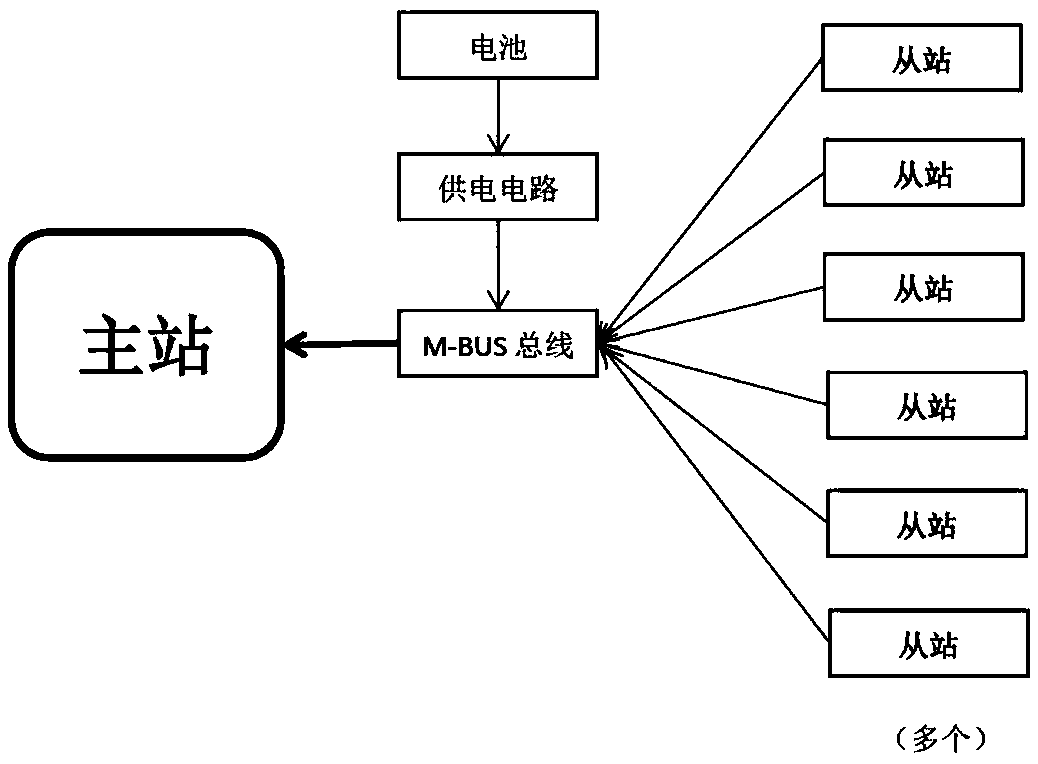
technical field [0001] The invention relates to the field of micro-power isolated power supply, in particular to a micro-power isolated power supply used for M-BUS power supply. Background technique: [0002] M-BUS is a bus design specially used for utility meters. The M-BUS instrument bus can meet the special requirements of battery-powered or remote-powered metering instruments. When the measuring instrument receives the data transmission request, it will transmit the current measured data to the master station, and the master station will periodically read the data transmitted by these measuring instruments. figure 1 It is a schematic diagram of the frame structure of M-BUS and bus, because M-BUS works almost only when the terminal measuring instrument or counter sends data, and transmits the data to the general station, and in most cases, M-BUS is in the "standby" state. Therefore, the working characteristics of the power supply circuit used for M-BUS are as follows: 1...

Claims


Application Information

Patent Timeline
Patent Type & Authority Applications(China)
IPC IPC(8): H02M3/335
CPCH02M3/33569
Inventor 张彦斌冯刚
Owner MORNSUN GUANGZHOU SCI & TECH
Learn More