
Short-wave infrared otoscope device, short-wave infrared otoscope system and detection method of ear fluid

A short-wave infrared and otoscope technology, applied in otoscopes, endoscopes, diagnostic records/measurements, etc., can solve problems such as misdiagnosis, inability to receive correct treatment for diseases, and limitations in the depth of visible light imaging

Pending Publication Date: 2018-10-19
王斯建
View PDF6 Cites 2 Cited by
  • Summary
  • Abstract
  • Description
  • Claims
  • Application Information

AI Technical Summary

Problems solved by technology

Although visible light can provide high resolution and high sensitivity, the transmission of visible light through the tympanic membrane is poor, and it also has strong attenuation at certain wavelengths, which greatly limits the imaging depth of visible light.
Therefore, using the existing otoscope based on visible light can only view the changes in the surface tissue of the patient's ear symptoms, but cannot detect the internal structure of the patient's ear canal, such as the ossicular chain of the middle ear structure behind the patient's tympanic membrane, bony promontory, round window niche Wait
Because the existing otoscope based on visible light cannot image the ear canal covered by the tympanic membrane in the patient's ear well, which has caused great obstacles to the doctor's diagnosis. Therefore, doctors can only rely on experience to diagnose in many cases. Under the circumstances, if the doctor is inexperienced, it is likely to make a misdiagnosis, resulting in the patient's illness not being treated correctly

Method used


Image

  • Short-wave infrared otoscope device, short-wave infrared otoscope system and detection method of ear fluid
  • Short-wave infrared otoscope device, short-wave infrared otoscope system and detection method of ear fluid
  • Short-wave infrared otoscope device, short-wave infrared otoscope system and detection method of ear fluid

Examples


Embodiment Construction

[0047] In order to better understand and illustrate the present invention, the present invention will be further described in detail below in conjunction with the accompanying drawings.

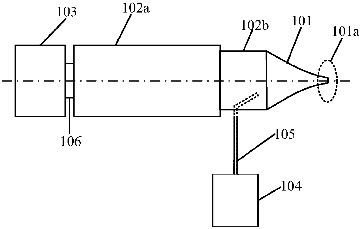
[0048] The invention provides a short-wave infrared otoscope device. Please refer to figure 1 , figure 1 It is a structural schematic diagram of a short-wave infrared otoscope device according to a specific embodiment of the present invention. As shown in the figure, the short-wave infrared otoscope device includes:

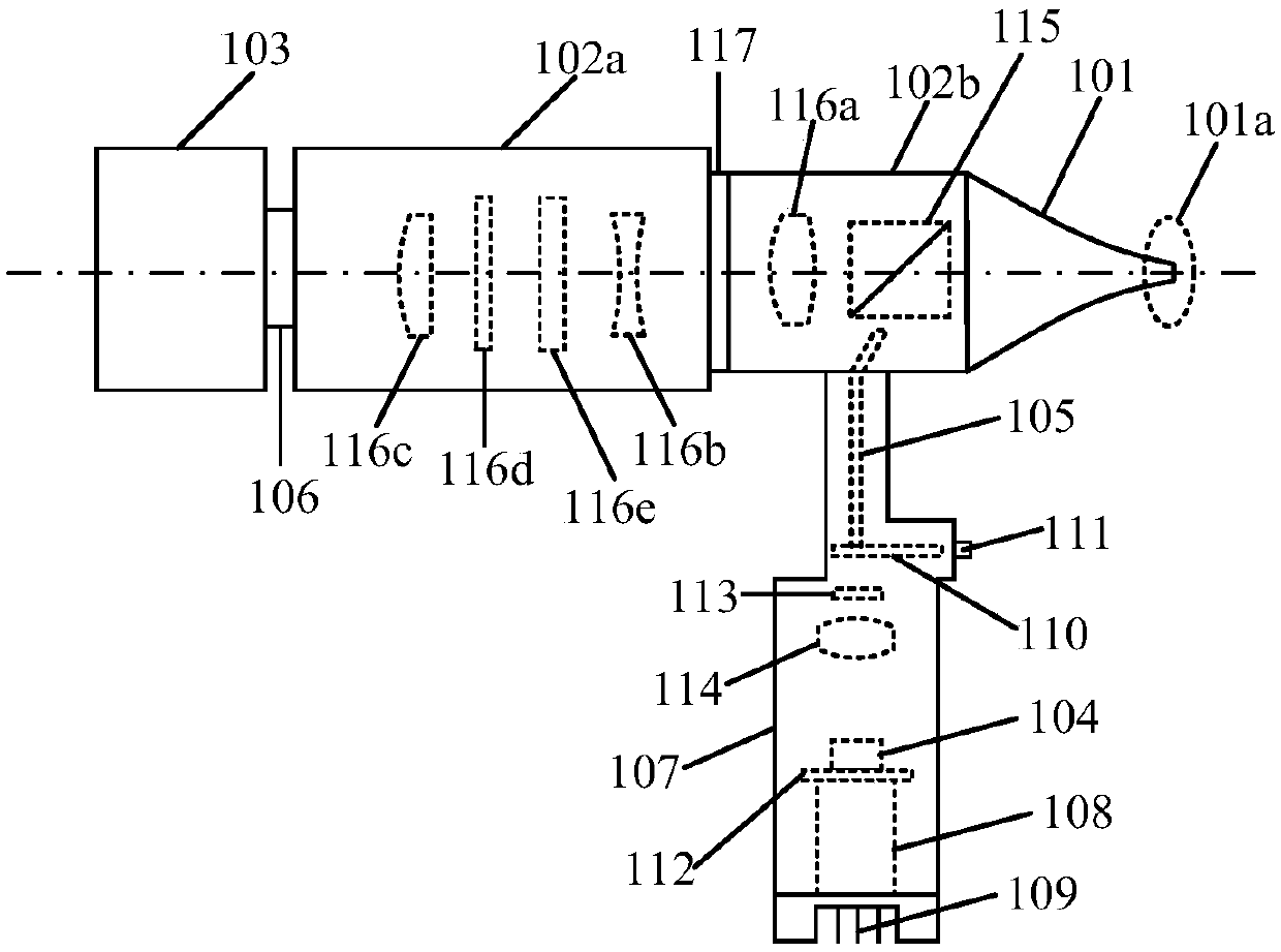
[0049] An illumination system, a speculum 101 with a peep opening 101a, a lens barrel with an optical system inside, and a short-wave infrared detector 103;

[0050] The lens barrel includes a lens barrel body 102a and a speculum adapter 102b, the speculum 101 is connected to one end of the lens barrel body 102a through the speculum adapter 102b, and the other end of the lens barrel body 102a is connected to the speculum adapter 102b. The short-wave infrared detector 103 is ...


PUM


Abstract

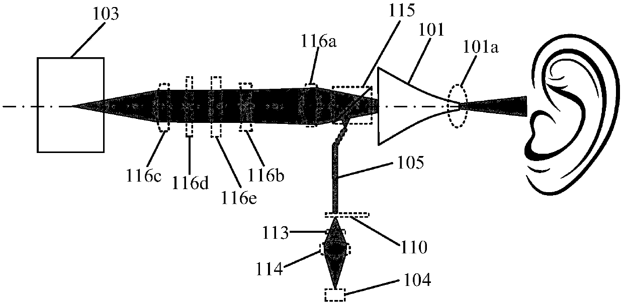
The invention provides a short-wave infrared otoscope device, which comprises an illumination system, a speculum, a lens barrel and a short-wave infrared detector. The lens barrel comprises a lens barrel body and a speculum adapter, wherein the speculum is connected with one end of the lens barrel body through the speculum adapter, and the other end of the lens barrel body is connected with a short-wave infrared detector; the illumination system comprises a light source and an optical fiber, wherein the light source is configured to emit short-wave infrared light, one end of the optical fiberis coupled with the light source, and the other end of the optical fiber is coupled with the speculum adapter; in operation, the light source emits short-wave infrared light, the optical fiber guidesthe short-wave infrared light into the speculum and enters the ear of the object to be detected from a speculum hole, the short-wave infrared light enters the speculum through the diffuse reflection light formed by the ear of the object to be detected from the speculum hole, and finally reaches the short-wave infrared detector to be imaged through the optical system in the lens barrel. Correspondingly, the invention also provides a short-wave infrared otoscope system and a detection method of ear fluid. In that embodiment of the invention, the inside of the ear of the object to be detected canbe better imaged.

Description

technical field [0001] The invention relates to the technical field of medical devices, in particular to a short-wave infrared otoscope device, a short-wave infrared otoscope system and an ear fluid detection method. Background technique [0002] In the prior art, visible light-based otoscopes are an important diagnostic tool for examination of a patient's external auditory canal and middle ear. Among the many visible light-based otoscopes, the air-drum otoscope is the most widely used. The inflatable otoscope is equipped with a visible light source and an air bag. When examining a patient's ear with an inflatable otoscope, the patient's ear is irradiated with visible light, and at the same time, the air bag is used to inflate the patient's ear. The doctor judges whether there is a middle ear lesion in the patient's ear based on the appearance of the patient's tympanic membrane under visible light, combined with the mobility of the otoscope or the air pressure felt by the ...

Claims


Application Information

Patent Timeline
Patent Type & Authority Applications(China)
IPC IPC(8): A61B1/227A61B1/06A61B5/00
CPCA61B1/00016A61B1/00034A61B1/00045A61B1/00163A61B1/0684A61B1/227A61B5/0086
Inventor 王斯建
Owner 王斯建
Learn More