Device for producing metal powder for 3D printing by gas atomization
A 3D printing and metal powder technology, which is applied in the field of atomization to prepare metal powder and powder metallurgy, to achieve the effects of narrowing the particle size range of the material, improving the efficiency of airflow, and increasing the area
- Summary
- Abstract
- Description
- Claims
- Application Information
AI Technical Summary
Problems solved by technology
Method used
Image

Examples
no. 1 example
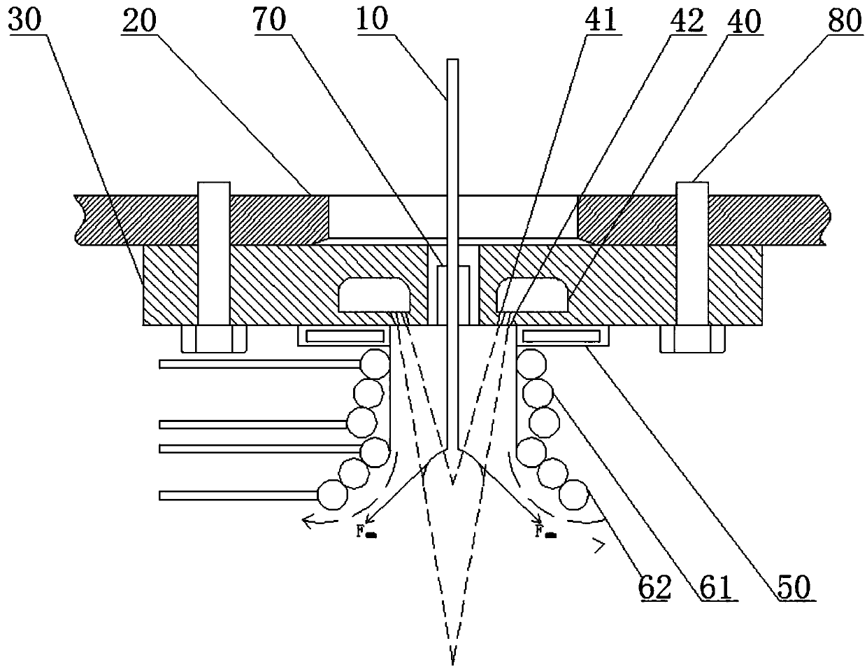
[0037] like figure 2 As shown, on the basis of the basic implementation, the first coil 61 is set as a frustum-shaped coil, the inner diameter of the top coil of the second coil 62 is smaller than the inner diameter of the first coil 61, and the cone angle of the first coil 61 is smaller than that of the second coil 61. The cone angle of the coil 62, the cone angle of the first coil 61 is between 30-50°. The purpose of setting the first coil into a truncated cone shape is to reduce the cross-interference of the magnetic force lines of the two coils.
no. 2 example
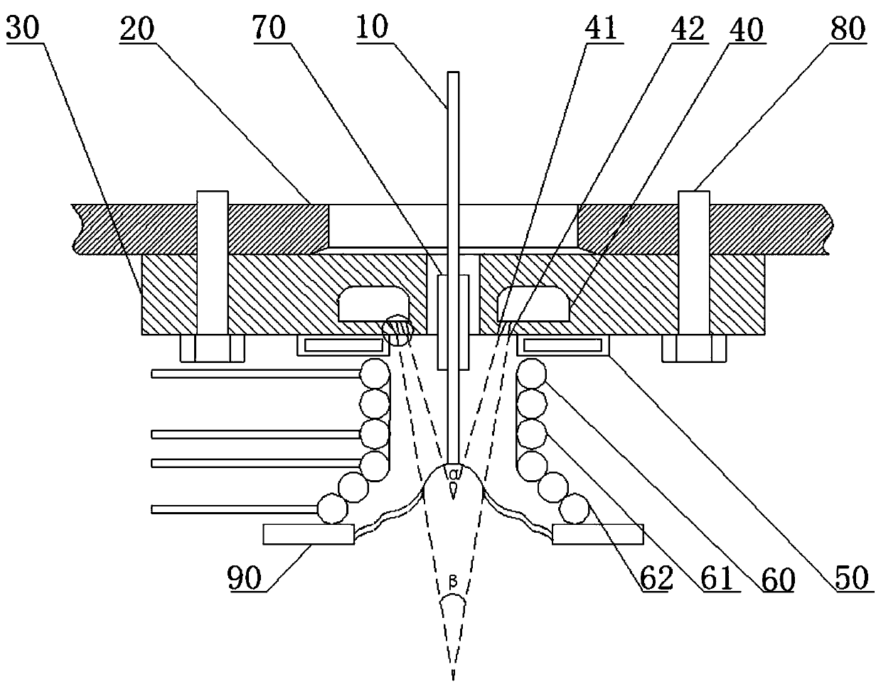
[0039] like image 3As shown, on the basis of the basic implementation, the technical solution of the first embodiment sets the first coil 61 as a cylindrical coil, and the inner diameter of the top coil of the second coil 62 is the same as the inner diameter of the first coil 61 . It also includes 2-4 microwave transmitters 90, the waveguides of which are located at the bottom of the second coil, and are evenly distributed along the horizontal circumference, and the center of the circle where they are located is located on the axis of the high-frequency induction coil 60, and the waveguide emission ports all point to the melting In the center, the outer surface of the waveguide is covered with an electromagnetic shielding layer. The electromagnetic shielding layer can be used alone. If the electromagnetic shielding film is used alone, the service life may be shorter due to high temperature. An additional layer of heat insulation layer is added on the electromagnetic shielding...
no. 3 example
[0042] like Figure 4 As shown, on the basis of the basic implementation, the technical solution of the first embodiment sets the first coil 61 as a cylindrical coil, and the inner diameter of the top coil of the second coil 62 is the same as the inner diameter of the first coil 61 . It also includes 2-4 microwave transmitters 90, the waveguide of which is located between the first and second coils, and is evenly distributed along the horizontal circumference, and the center of the circle where it is located is located on the axis of the high-frequency induction coil 60, and the waveguide emits The ports all point to the melting center, and the outer surface of the waveguide is covered with an electromagnetic shielding layer. The electromagnetic shielding layer can be used alone. If the electromagnetic shielding film is used alone, the service life may be shorter due to high temperature. An additional layer of heat insulation layer is added on the electromagnetic shielding fil...
PUM
| Property | Measurement | Unit |
|---|---|---|
| angle | aaaaa | aaaaa |
| diameter | aaaaa | aaaaa |
Abstract
Description
Claims
Application Information
 - R&D
- Intellectual Property
- Life Sciences
- Materials
- Tech Scout
- Unparalleled Data Quality
- Higher Quality Content
- 60% Fewer Hallucinations
Browse by: Latest US Patents, China's latest patents, Technical Efficacy Thesaurus, Application Domain, Technology Topic, Popular Technical Reports.
© 2025 PatSnap. All rights reserved.Legal|Privacy policy|Modern Slavery Act Transparency Statement|Sitemap|About US| Contact US: help@patsnap.com