Portable aircraft skin drilling device

A technology for aircraft skin and drilling device, which is applied in portable drilling rigs, feeding devices, boring/drilling and other directions, can solve the problems that the assembly method cannot meet the requirements, the absolute positioning accuracy is low, the volume and weight are large, and the weight is reached. Light, compact and small effect

Active Publication Date: 2018-10-19
NORTHEASTERN UNIV
View PDF7 Cites 8 Cited by
  • Summary
  • Abstract
  • Description
  • Claims
  • Application Information

AI Technical Summary

Problems solved by technology

[0002] Manual assembly is used in aircraft assembly in my country, and with the continuous improvement of aircraft performance requirements, this traditional assembly method can no longer meet the requirements
Most of the existing aircraft skin drilling technologies use the end-loading automatic drilling and riveting system of industrial manipulators, but both industrial manipulators and automatic drilling and riveting systems have the disadvantages of large equipment volume and weight, low rigidity, low flexibility, high cost, and low absolute positioning accuracy. shortcoming

Method used


Image

  • Portable aircraft skin drilling device
  • Portable aircraft skin drilling device
  • Portable aircraft skin drilling device

Examples


Embodiment 1

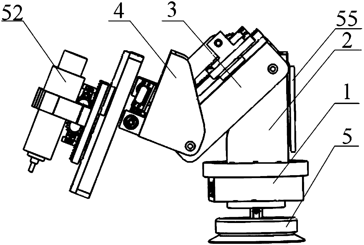
[0078] Such as figure 1 Shown: the present embodiment provides a kind of portable aircraft skin drilling device, and this device comprises:

[0079] Base 1, column 2, extension arm 3, rotating arm 4 and drilling mechanism 52;

[0080] The first end of the base 1 is provided with a suction cup 5 for fixing the portable aircraft skin drilling device. the first turntable 12;

[0081] The second end of the column 2 is movably connected with the first end of the extension arm 3; the second end of the extension arm 3 is movably connected with the first end of the rotating arm 4;

[0082] The second end of the rotating arm 4 is provided with a second turntable 41 , and the second turntable 41 is provided with a drilling mechanism, and the drilling mechanism 52 moves linearly on the second turntable 12 .

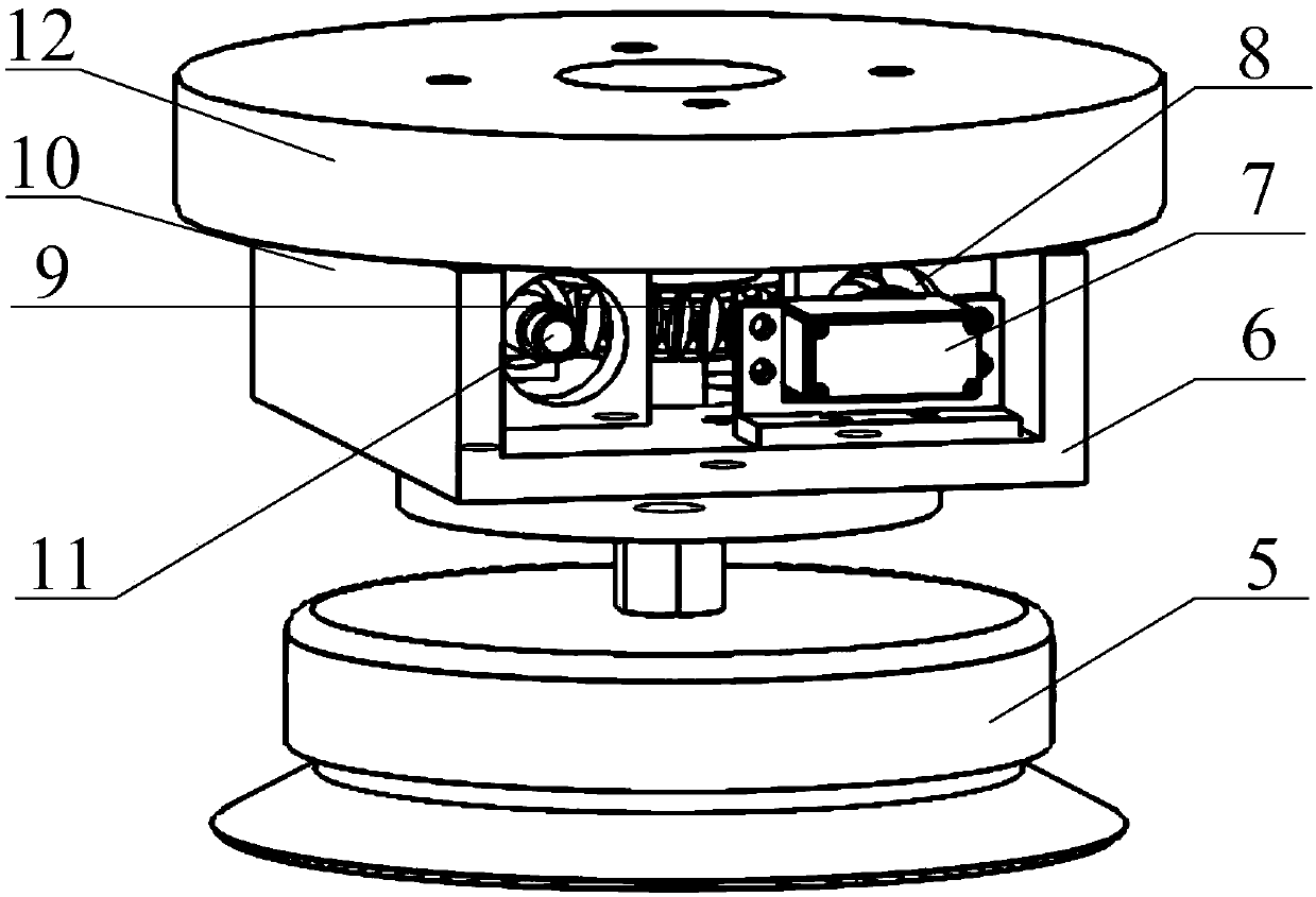
[0083] Optionally, base 1 also includes:

[0084] The first rotating mechanism and the base rotating shaft frame 6;

[0085] Wherein, the first rotating mechanism includes: a w...

Embodiment 2

[0125] In the specific implementation process, the mechanism of the device in this embodiment is as follows: figure 1 shown, refer to Figure 8 As shown, in this embodiment, the connecting flange 55 of the manipulator is fixedly connected to the second side 106 of the vertical column vertical plate perpendicular to the second turntable; the connecting flange 55 of the manipulator is connected to the manipulator;

[0126] For example, the manipulator can be a manipulator of any existing robot, which is not limited in this embodiment, and any manipulator that can perform mechanical actions can be the manipulator of this embodiment.

[0127] The working process of this embodiment is specifically as follows:

[0128] When drilling for high and far areas, the device of this embodiment can be connected with the manipulator through the connecting flange 55;

[0129]Before the drilling process, the present invention is first placed on the specified position of the aircraft skin with...


PUM


Abstract

The invention provides a portable aircraft skin drilling device, and specifically belongs to the field of industrial manipulators. The device comprises a base, a vertical column, an extending arm, a rotating arm and a drilling mechanism, wherein a chuck for fixing is arranged at the first end of the base, and a second rotating platform is arranged at the second end of the base and is fixedly connected to the first end of the vertical column; the second end of the vertical column is movably connected to the first end of the extending arm, and the second end of the extending arm is movably connected to the first arm of the rotating arm; a second rotating platform is arranged on the second end of the rotating arm, and the drilling mechanism is arranged on the second rotating platform and linearly moves on the surface of the second rotating platform. The whole device is compact and small in structure, convenient to operate and carry, and simple in structure, and meets the demand o drillingin the surface of a skin with a complex shape.

Description

technical field [0001] The invention belongs to the field of industrial manipulators, in particular to a portable aircraft skin drilling device. Background technique [0002] Manual assembly is used in aircraft assembly in our country, and with the continuous improvement of aircraft performance requirements, this traditional assembly method can no longer meet the requirements. Most of the existing aircraft skin drilling technologies use the end-loading automatic drilling and riveting system of industrial manipulators, but both industrial manipulators and automatic drilling and riveting systems have the disadvantages of large equipment volume and weight, low rigidity, low flexibility, high cost, and low absolute positioning accuracy. shortcoming. [0003] In view of the state of the prior art proposed above and the current industry demand for aircraft skin drilling technology, there is an urgent need for an aircraft skin drill with high rigidity, small size, light weight, co...

Claims


Application Information

Patent Timeline
IPC IPC(8): B23B41/00B23B47/26B23B47/20B23B47/30B23B45/14
CPCB23B41/00B23B47/26B23B47/30B23Q5/385B23Q9/0007
Inventor 房立金于晓蕾
Owner NORTHEASTERN UNIV
Why Eureka
Try Eureka