Truss manipulator for stamping carrying and material taking

A technology of manipulators and trusses, applied in the field of truss manipulators, can solve problems such as poor stability, easy deformation, long travel time, etc.

Pending Publication Date: 2022-08-02
苏州大得机械科技有限公司
View PDF0 Cites 0 Cited by
  • Summary
  • Abstract
  • Description
  • Claims
  • Application Information

AI Technical Summary

Problems solved by technology

[0003] Existing truss manipulators have certain disadvantages in use. First of all, when in use, the operation is more troublesome, the fuselage strength is poor, and it is prone to deformation. It has certain noise and poor stability, which is not conducive to people. In addition, when using it, the travel time is longer and the production cycle is shorter, which has brought certain adverse effects on people's use process. Therefore, we propose a truss manipulator for stamping, handling and reclaiming.

Method used


Image

  • Truss manipulator for stamping carrying and material taking
  • Truss manipulator for stamping carrying and material taking
  • Truss manipulator for stamping carrying and material taking

Examples


Embodiment 1

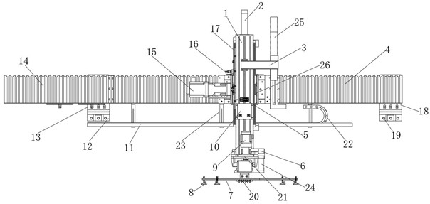
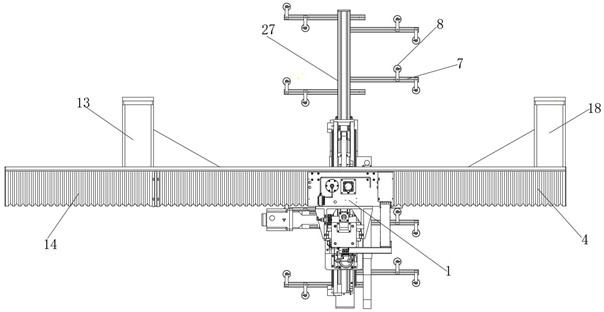
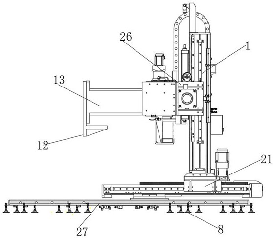
[0026] like Figure 1-4 As shown, a truss manipulator for punching, handling and reclaiming includes a Z-axis aluminum alloy box body 1, a positioning and mounting connection seat 26 is installed on the Z-axis aluminum alloy box body 1, and one end of the positioning and mounting connection seat 26 is installed with a left organ The plate 14, the other end of the positioning and installation connecting seat 26 is installed with the right organ plate 4, the rear end of the left organ plate 14 is installed with a No. X-axis main beam 13, and the rear end of the No. 1 X-axis main beam 13 is installed with a No. , the rear end of the right organ plate 4 is installed with the No. 2 X-axis main beam 18, the rear end of the No. 2 X-axis main beam 18 is installed with a No. 2 mounting plate 19, and the bottom front end of the Z-axis aluminum alloy box 1 is installed with a Y-axis Motor 9.

[0027] Further, the Z-axis aluminum alloy box 1 and the positioning and installation connectin...

Embodiment 2

[0029] On the basis of Example 1, as Figure 1-4 As shown, a truss manipulator for punching, handling and reclaiming includes a Z-axis aluminum alloy box body 1, a positioning and mounting connection seat 26 is installed on the Z-axis aluminum alloy box body 1, and one end of the positioning and mounting connection seat 26 is installed with a left organ The plate 14, the other end of the positioning and installation connecting seat 26 is installed with the right organ plate 4, the rear end of the left organ plate 14 is installed with a No. X-axis main beam 13, and the rear end of the No. 1 X-axis main beam 13 is installed with a No. , the rear end of the right organ plate 4 is installed with the No. 2 X-axis main beam 18, the rear end of the No. 2 X-axis main beam 18 is installed with a No. 2 mounting plate 19, and the bottom front end of the Z-axis aluminum alloy box 1 is installed with a Y-axis Motor 9.

[0030]Further, a Z-axis balance cylinder 2 is installed on the top po...

Embodiment 3

[0033] On the basis of Embodiment 1 and Embodiment 2, as Figure 1-4 As shown, a truss manipulator for punching, handling and reclaiming includes a Z-axis aluminum alloy box body 1, a positioning and mounting connection seat 26 is installed on the Z-axis aluminum alloy box body 1, and one end of the positioning and mounting connection seat 26 is installed with a left organ The plate 14, the other end of the positioning and installation connecting seat 26 is installed with the right organ plate 4, the rear end of the left organ plate 14 is installed with a No. X-axis main beam 13, and the rear end of the No. 1 X-axis main beam 13 is installed with a No. , the rear end of the right organ plate 4 is installed with the No. 2 X-axis main beam 18, the rear end of the No. 2 X-axis main beam 18 is installed with a No. 2 mounting plate 19, and the bottom front end of the Z-axis aluminum alloy box 1 is installed with a Y-axis Motor 9.

[0034] Further, an installation base 21 is instal...


PUM


Abstract

The truss manipulator comprises a Z-axis aluminum alloy box body, a positioning installation connecting base is installed on the Z-axis aluminum alloy box body, a left organ plate is installed at one end of the positioning installation connecting base, and a right organ plate is installed at the other end of the positioning installation connecting base; a first X-axis main cross beam is installed at the rear end of the left organ plate. The truss manipulator for stamping carrying and material taking is special mechanical equipment designed for stamping carrying and material taking, the manipulator is divided into an upper shaft, a lower shaft, a left shaft and a right shaft, the front shaft and the rear shaft are driven by high-precision servo, vacuum negative-pressure adsorption materials are grabbed and can be replaced by electromagnets, advanced PLC control is applied, a touch screen is adopted as a human-computer interface, and the manipulator is high in automation degree. The machine body is bent and welded, the strength is high, the deformation is small, the sliding block is low in noise and good in stability, and the absolute value servo motor is matched with the planetary precision speed reducer, so that the transmission precision is good.

Description

technical field [0001] The invention relates to the field of truss manipulators, in particular to a truss manipulator for punching, handling and material reclaiming. Background technique [0002] The truss manipulator is a kind of support equipment for material handling. It is a special mechanical equipment designed for stamping handling and reclaiming. With the continuous development of science and technology, people have higher and higher requirements for the manufacturing process of truss manipulators. [0003] The existing truss manipulator has certain drawbacks in use. First of all, when using it, the operation is troublesome, the strength of the body is poor, the deformation is easy to occur, there is a certain noise, and the stability is poor, which is not conducive to people. In addition, when using it, the travel time is long and the production cycle is short, which brings certain adverse effects to people's use process. For this reason, we propose a truss manipula...

Claims


Application Information

Patent Timeline
Patent Type & Authority Applications(China)
IPC IPC(8): B21D43/18
CPCB21D43/18Y02P70/10
Inventor 周铭
Owner 苏州大得机械科技有限公司
Why Eureka
Try Eureka