Ball park service robot
A technology of service robots and courts, applied in the field of intelligent robots, can solve the problems of lack of popularity, slow development, high purchase and maintenance costs, etc.
- Summary
- Abstract
- Description
- Claims
- Application Information
AI Technical Summary
Problems solved by technology
Method used
Image
Examples
Embodiment 1
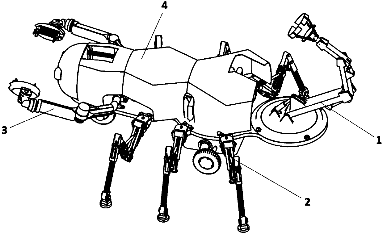
[0081] Embodiment 1: as Figure 1-41 As shown, the stadium service robot is characterized in that it includes a ball throwing device 1, a locomotive traveling device 2, a ball catching mechanism 3, and a machine body 4. The ball throwing device 1 is arranged at the rear end of the machine body 4, and the locomotive traveling device 2 is arranged on the machine body 4 In the middle, the ball-catching mechanism 3 is arranged at the front end of the machine body 4;
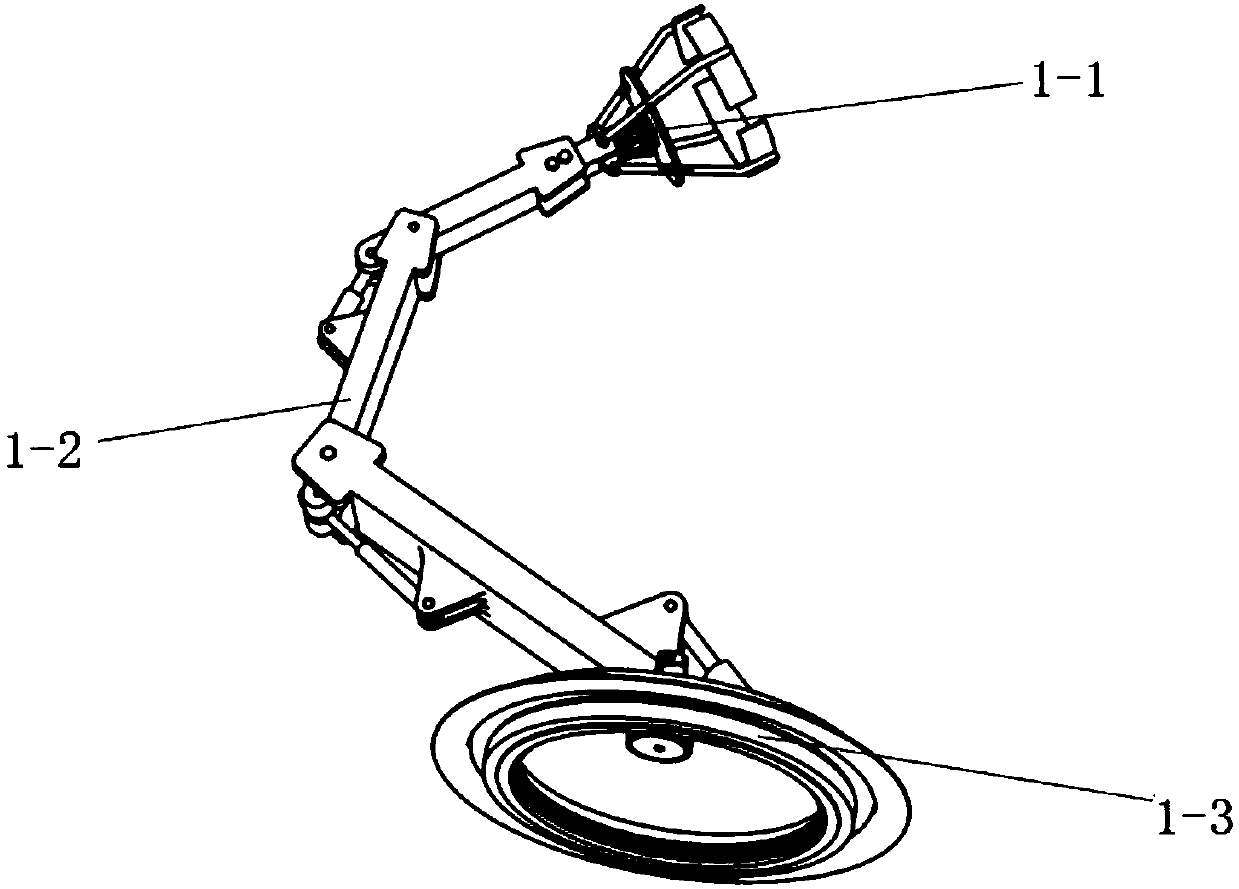
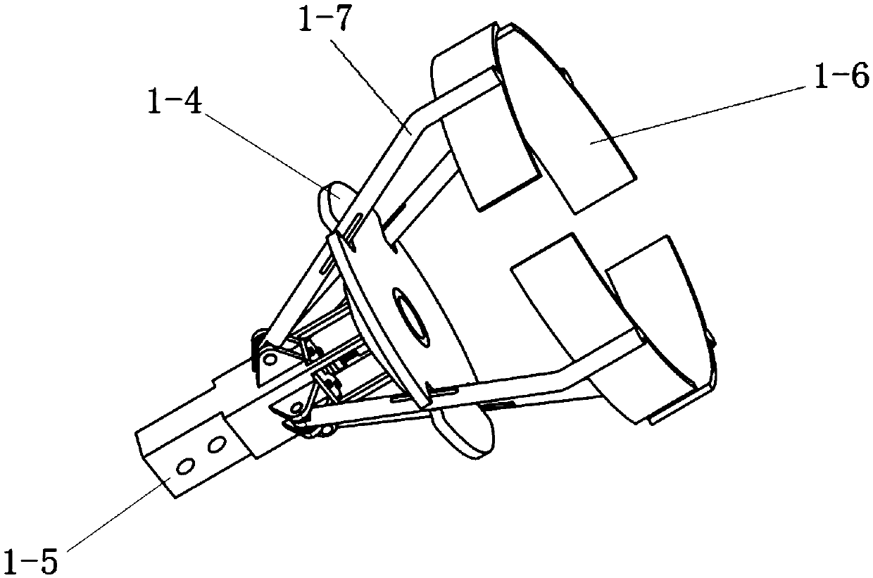
[0082] Wherein the ball throwing device 1 comprises a throwing port 1-1, a multi-axis mechanical arm I1-2, a bottom rotating mechanism 1-3, the ball throwing port 1-1 is installed on the upper end of the multi-axis mechanical arm I1-2, and a bottom rotating mechanism 1- 3 Installed on the lower end of the multi-axis mechanical arm I1-2; the ball throwing port 1-1 includes a push plate 1-4, a push device 1-5, 4 cladding plates 1-6, 4 guide rods 1-7, The pushing device 1-5 includes coupling I1-8, push rod 1-9, lead sc...
Embodiment 2
[0086] Embodiment 2: as Image 6 , 8 , Shown in 20,28-31,33-35, present embodiment structure is the same as embodiment 1, and difference is: have motor installation slot 1-20 on the supporting base 1-12 of throwing mouth, and motor 1-11 is installed on In the motor installation groove 1-20; there is a guide groove 1-27 on the guide rod 1-7, there are 4 guide rod installation grooves 1-28 on the push plate 1-4, and there are Shaft I 1-29, shaft I is set in the guide groove 1-27 and moves along it; two gear train end covers 2-29 are arranged on both sides of the gear train box and are located outside the two ends of the differential shaft 2-40; The two-axis arm 3-23 in the two-axis mechanical arm II3-2 is a hollow tube composed of the two-axis arm I3-12 and the two-axis arm II3-13. One end of the two-axis arm II3-13 is fixed to the RV reducer II3-21. The other end is fixedly connected with the RV reducer Ⅰ3-19, and the two-axis arm Ⅰ3-12 is installed on the two-axis arm Ⅱ3-13;...
Embodiment 3
[0087] Embodiment 3: as Figure 36 , 37 Shown, present embodiment structure is the same as embodiment 1, and difference is: dribble box 4-3 bottom is provided with slideway 4-12, has slide rail at the bottom of spring box, and slide rail is arranged in the slideway and moves along it, Have screw rod installation hole 4-13 and guide rail installation hole 4-14 on the dribble box, have screw thread in the leading screw installation hole 4-14 and match with leading screw II; The storage battery 5 is connected with components requiring power supply in a conventional manner and provides energy.
PUM
 Abstract
Description
Claims
Application Information
 - R&D
- Intellectual Property
- Life Sciences
- Materials
- Tech Scout
- Unparalleled Data Quality
- Higher Quality Content
- 60% Fewer Hallucinations
Browse by: Latest US Patents, China's latest patents, Technical Efficacy Thesaurus, Application Domain, Technology Topic, Popular Technical Reports.
© 2025 PatSnap. All rights reserved.Legal|Privacy policy|Modern Slavery Act Transparency Statement|Sitemap|About US| Contact US: help@patsnap.com


