Plastic film cutting making device

A technology of plastic film and edge banding device, which is applied in the field of plastic film production, can solve the problems of increasing the labor load of workers, varying the length of plastic films, and consuming labor costs, and achieves the advantages of easy replacement, reduced economic costs, and improved production efficiency Effect

Inactive Publication Date: 2018-10-19
刘林平
View PDF0 Cites 2 Cited by
  • Summary
  • Abstract
  • Description
  • Claims
  • Application Information

AI Technical Summary

Problems solved by technology

[0002] All kinds of bags, boxes, sleeves, envelopes, etc. made of paper, aluminum foil, fiber, plastic film and their composites are flexible packaging. In recent years, plastic products have been widely used, especially film-type plastic bags, plastic For products such as woven bags, the plastic film is transparent and flexible, has good water resistance, oil resistance, moisture resistance and barrier properties, good mechanical strength, stable chemical properties, and is easy to print exquisite pictures and texts. It can be heat-sealed to make bags, and can meet The packaging requirements of various items are ideal flexible packaging materials for packaging food and daily necessities that are easy to store and store. These plastic products bring us a convenient life. In the production process, we need to carry out plastic film Cutting is convenient for us to use. In the prior art, when manual operation is performed, because the plastic film is too soft and inconvenient to fix, the plastic film is prone to problems such as different lengths, uncontrollable sizes, labor costs, etc., and there are cutting devices. Most of the materials are manually operated, which increases the labor workload of the workers, and the work efficiency is low

Method used


Image

  • Plastic film cutting making device
  • Plastic film cutting making device
  • Plastic film cutting making device

Examples


Embodiment Construction

[0019] The following will clearly and completely describe the technical solutions in the embodiments of the present invention with reference to the accompanying drawings in the embodiments of the present invention. Obviously, the described embodiments are only some, not all, embodiments of the present invention. Based on the embodiments of the present invention, all other embodiments obtained by persons of ordinary skill in the art without making creative efforts belong to the protection scope of the present invention.

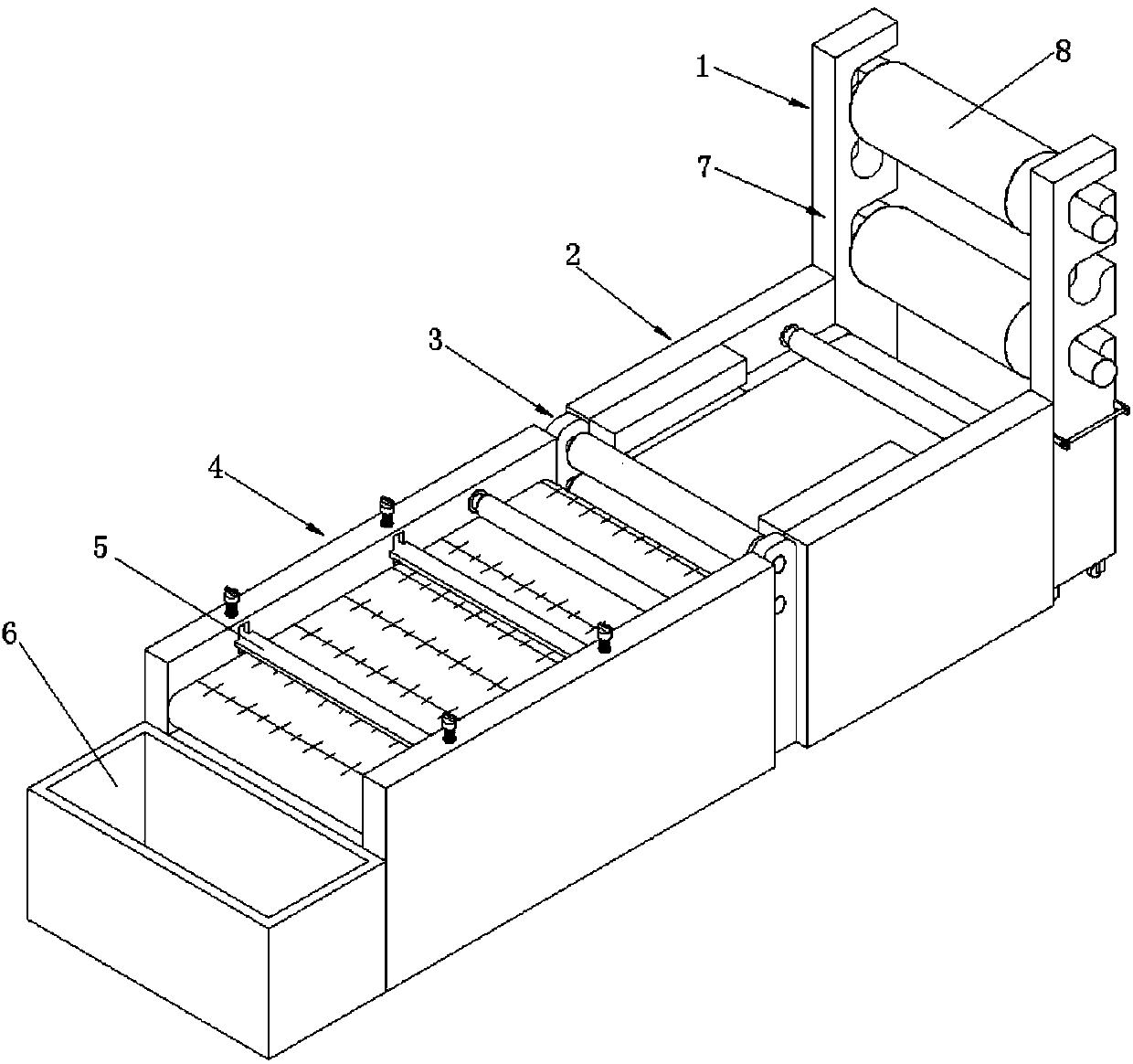
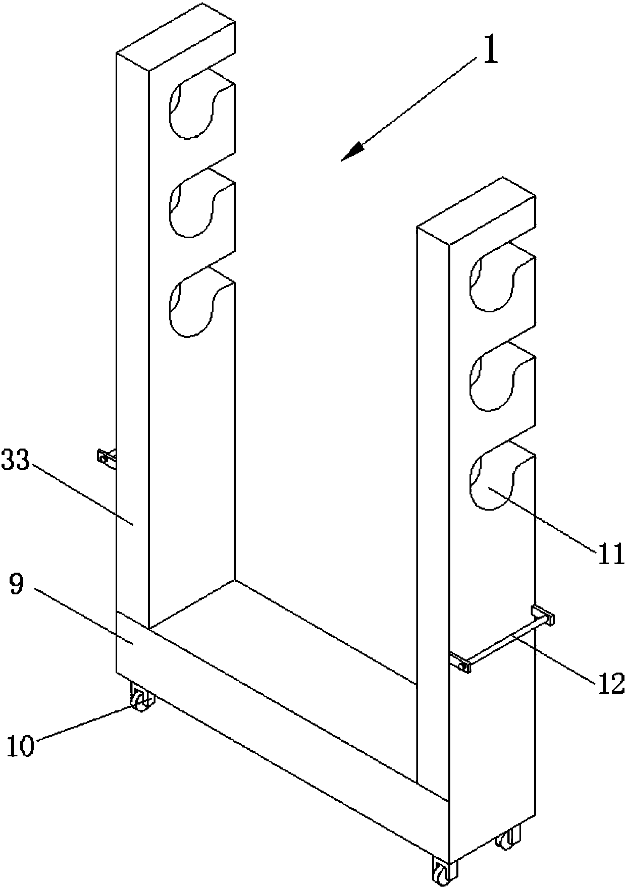
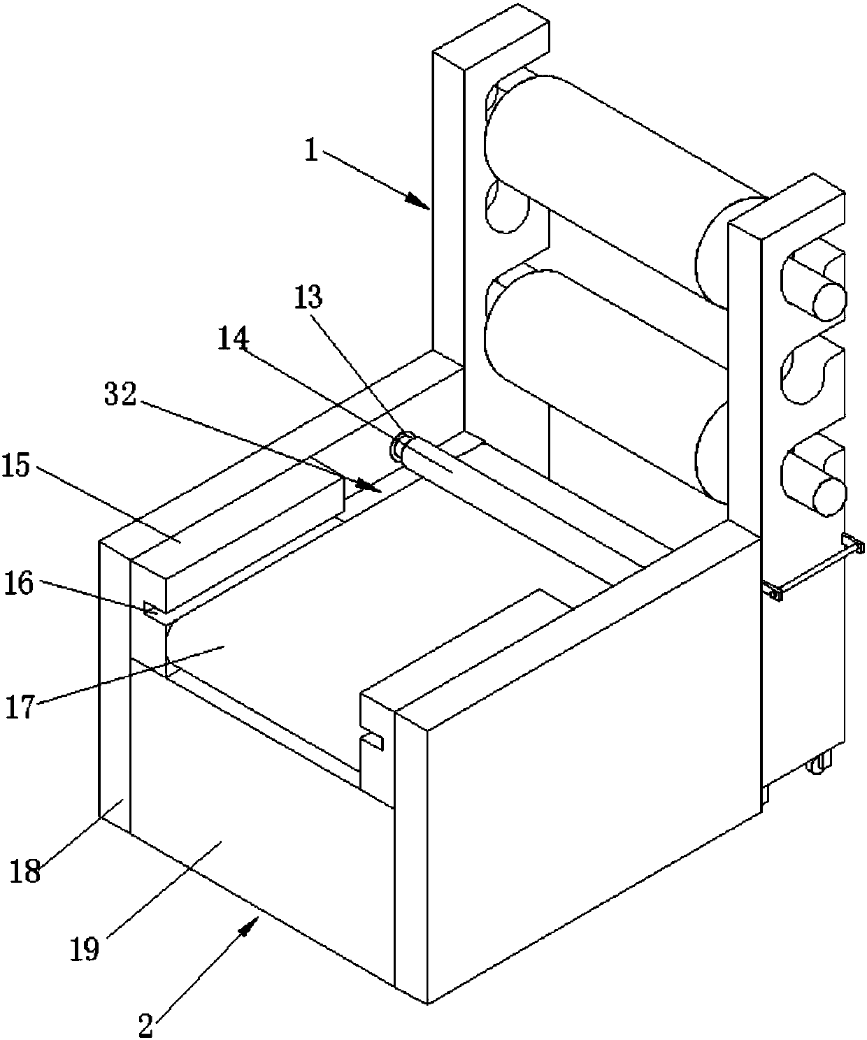
[0020] The present invention provides such as Figure 1-5 A plastic film cutting device shown includes a feeding device 1, an edge sealing device 2, a feeding group 3 and a cutting group 4, and the edge sealing device 2 includes a first side plate 18 and is connected and fixed to the first side plate. The first base 19 at the position of the side plate 18, the first base 19 is provided with a first conveyor belt 17, and the first conveyor belt 17 is arranged o...


PUM


Abstract

The invention discloses a plastic film cutting making device. The plastic film cutting making device comprises a feeding device, an edge sealing device, a feeding set and a cutting set. The edge sealing device comprises first side plates and a first base connecting and fixing the positions of the first side plates. The first base is provided with a first conveying belt. The first conveying belt isarranged on the upper end face of the first base. The first conveying belt moves in the front-back direction along the first base. The first side plates are hinged to the left side edge and the rightside edge of the first base. The rear side of the edge sealing device is connected with the feeding device. The cutting set is arranged on the front side of the edge sealing device. The feeding set is connected between the edge sealing device and the cutting set. The front side of the cutting set is connected with a material collecting box. The feeding device is provided with a supporting frame and raw material rollers. The supporting frame is supported and fixed to the raw material rollers. According to the plastic film cutting making device, product specification uniformity is guaranteed, automatic feeding is conducted, the economic cost is reduced, and the production efficiency is improved.

Description

technical field [0001] The invention belongs to the technical field of plastic film production, and in particular relates to a plastic film cutting device. Background technique [0002] All kinds of bags, boxes, sleeves, envelopes, etc. made of paper, aluminum foil, fiber, plastic film and their composites are flexible packaging. In recent years, plastic products have been widely used, especially film-type plastic bags, plastic For products such as woven bags, the plastic film is transparent and flexible, has good water resistance, oil resistance, moisture resistance and barrier properties, good mechanical strength, stable chemical properties, and is easy to print exquisite pictures and texts. It can be heat-sealed to make bags, and can meet The packaging requirements of various items are ideal flexible packaging materials for packaging food and daily necessities that are easy to store and store. These plastic products bring us a convenient life. In the production process, w...

Claims


Application Information

Patent Timeline
Patent Type & Authority Applications(China)
IPC IPC(8): B26D7/01B26D7/06B26D7/02B31B70/20B31B70/02
CPCB26D7/015B26D7/025B26D7/0625B31B70/02B31B70/20
Inventor 刘林平
Owner 刘林平
Why Eureka
Try Eureka