Combined pneumatic dry-type friction clutch brake for forging machine

A friction clutch and combined technology, which is applied in the direction of brake type, brake parts, coupling and brake combination, etc., can solve the problems of asynchronous movement, inconsistent wear, cylinder wear, etc., and achieve good impact resistance and reduce Cost of production input, consistent effect of wear

Pending Publication Date: 2018-10-19
ANHUI LIYUAN NUMERICAL CONTROL CUTTING TOOL & PATTERNS MFG
View PDF7 Cites 1 Cited by
  • Summary
  • Abstract
  • Description
  • Claims
  • Application Information

AI Technical Summary

Problems solved by technology

[0007] At present, the existing split-type friction block has the problem of inconsistent wear due to asynchronous movement, which causes the cylinder or body to wear and has to be replaced. The purpose of the present invention is to provide a combined pneumatic dry friction clutch brake for forging machinery. The blocks can basically move synchronously, which ensures that the wear of the friction blocks is relatively consistent. During maintenance, only the friction blocks need to be replaced, which reduces the production input cost of the enterprise

Method used


Image

  • Combined pneumatic dry-type friction clutch brake for forging machine
  • Combined pneumatic dry-type friction clutch brake for forging machine
  • Combined pneumatic dry-type friction clutch brake for forging machine

Examples


Embodiment 1

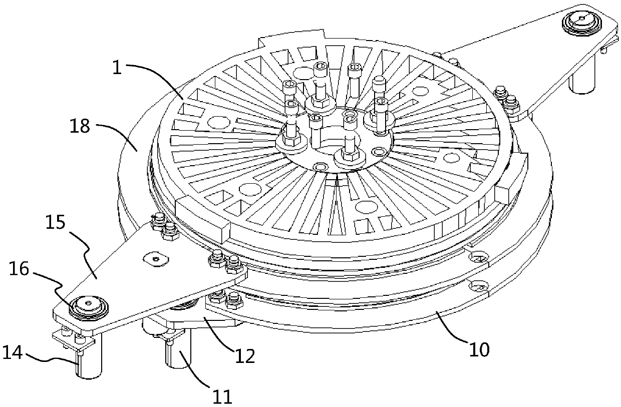
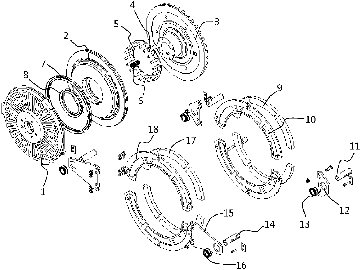
[0038] Please refer to Figure 1 to Figure 6 , the combined pneumatic dry friction clutch brake for forging machinery of this embodiment includes a clutch disc 10, a first friction block 9 and a brake disc 18 arranged on the clutch disc 10, and a second friction block arranged on the brake disc 18. The friction block 17, wherein the disc surface of the clutch disc 10 is provided with a plurality of strip-shaped through holes along the circumferential direction, and the first fixed magnetic pole pieces 101 are arranged around the strip-shaped through holes. The first fixed magnetic pole pieces 101 include N poles and S poles. A first movable magnetic pole piece 91 is provided around a friction block 9, and the first movable magnetic pole piece 91 includes N poles and S poles opposite to the N pole and S pole positions of the first fixed magnetic pole piece 101, and the gap between the first friction block 9 is Cooperately placed in the strip-shaped through-holes; the disc surfa...

Embodiment 2

[0043] The structure of this embodiment is basically the same as that of Embodiment 1, the difference is that, as figure 2 , Figure 4 with Image 6 As shown, the structural shapes of the clutch disc 10 and the brake disc 18 are consistent. For the convenience of installation, they are composed of two semi-circular plates. The connecting part of the brake disc 18 is fixed by the other connecting part of the machine tool through the brake pin 14, the brake ear plate 15 and the brake joint bearing 16.

[0044] The material of the clutch disc 10 and the brake disc 18 is cast iron, and the cast iron is Q235 cast iron, Q400 cast iron or Q450 cast iron. Cast iron has good heat transfer function. In addition, cast iron has good toughness and good impact resistance. 10 or on the circumference of the brake disc 18, three equidistant bar-shaped through holes are evenly distributed.

Embodiment 3

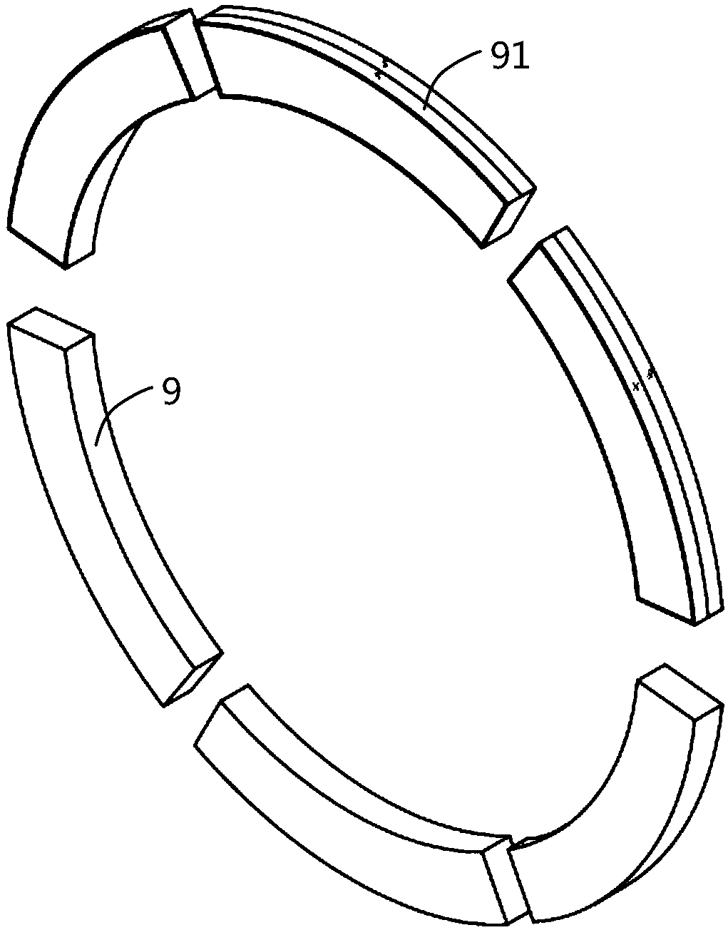
[0046] The structure of this embodiment is basically the same as that of Embodiment 1, the difference is that, as figure 2 , image 3 with Figure 5 As shown, the structural shapes of the first friction block 9 and the second friction block 17 are consistent, and are in the shape of an annular sheet. The first friction block 9 includes a first base body, and a first movable magnetic pole is wrapped and bonded around the first base body. The sheet 91 ; the second friction block 17 includes a second base body, and a second movable magnetic pole piece 171 is wrapped and bonded around the second base body.

[0047] In this embodiment, the thickness of the first movable magnetic pole piece 91 is consistent with the thickness of the clutch disc 10; the thickness of the second movable magnetic pole piece 171 is consistent with the thickness of the brake disc 18, and the N pole and the S pole are evenly separated, The first friction block 9 and the second friction block 17 move the...


PUM


Abstract

The invention discloses a combined pneumatic dry-type friction clutch brake for a forging machine, and belongs to the technical field of clutches. The combined pneumatic dry-type friction clutch brakecomprises a clutch disc, first friction blocks, a brake disc and second friction blocks; a plurality of strip-shaped through holes are formed in the disc face of the clutch disc in the circumferential direction, first fixed magnetic pole pieces comprising N poles and S poles are arranged around the strip-shaped through holes, first movable magnetic pole pieces with opposite N poles and S poles are arranged around the first friction blocks, and the first friction blocks are arranged in the strip-shaped through holes in a clearance fit mode; and a plurality of strip-shaped through holes are formed in the disc face of the brake disc in the circumferential direction, second fixed magnetic pole pieces comprising N poles and S poles are arranged around the strip-shaped through holes, second movable magnetic pole pieces with opposite N poles and S poles are arranged around the second friction blocks, and the second friction blocks are arranged in the strip-shaped through holes in a clearancefit mode. Therefore, the first friction blocks and the second friction blocks can move towards one side quickly and basically synchronously, and it is ensured that abrasion of the friction blocks isconsistent.

Description

technical field [0001] The invention belongs to the technical field of clutches, and more specifically relates to a combined pneumatic dry friction clutch brake for forging machinery, which is used for clutching or braking of non-land vehicle operating equipment, and plays a role in controlling and controlling the moving slider. The effect of rapid stop, such as some low-speed forging machinery, including forging hammers for forming, mechanical presses, hydraulic presses, screw presses and flat forging machines, as well as auxiliary equipment such as uncoilers, straightening machines, shearing machines, forging operators, etc. , to control and quickly stop the motion slider. Background technique [0002] Pneumatic clutch brakes rely on air pressure to push friction components to transmit power, and release them by return springs. At present, pneumatic clutches are mainly used between shafts that need to generate separation and engagement motions, and transmit power. The br...

Claims


Application Information

Patent Timeline
Patent Type & Authority Applications(China)
IPC IPC(8): F16D67/04F16D69/00F16D65/12F16D65/18F16D65/847F16D121/04F16D125/04
CPCF16D65/125F16D65/18F16D65/847F16D67/04F16D69/00F16D2065/789F16D2121/04F16D2125/04
Inventor 张迎年张先进
Owner ANHUI LIYUAN NUMERICAL CONTROL CUTTING TOOL & PATTERNS MFG
Why Eureka
Try Eureka