Hydrogen sealing device and sealing method of steam turbine generator set

A steam turbine generator set, hydrogen sealing technology, applied in the direction of engine sealing, engine components, mechanical equipment, etc., can solve the problems of inability to realize the follow-up of pads and journals, unstable vibration, and generator insulation decline, etc. Improve unstable vibration phenomenon, reduce jamming phenomenon, small leakage effect

Pending Publication Date: 2018-10-19
CENT CHINA BRANCH OF CHINA DATANG CORP SCI & TECH RES INST CO LTD
View PDF0 Cites 2 Cited by
  • Summary
  • Abstract
  • Description
  • Claims
  • Application Information

AI Technical Summary

Problems solved by technology

[0004] There are the following problems in the application of circular flow sealing tiles in hydrogen-cooled generator sets: (1) The floating force is not enough
After the hydrogen pressure of the generator increases, the pressure difference between the hydrogen side and the air side becomes larger. After the hydrogen pressure acts on the end face of the sealing ring, an axial thrust will be formed to push the sealing ring to one side, causing tiles to be stuck. (2) After sealing the tile, it will not only cause the temperature of the tile to rise, but also cause unstable vibration; (3) Seal the gap between the pads not too small
If the gap between the sealing tiles is too small, the temperature of the tiles will rise. When the gap between the sealing tiles increases, not only the leakage of hydrogen gas, but also the flow rate of the sealing oil will increase. The sealing oil may flow back into the generator body, resulting in insulation drop and other failures

Method used


Image

  • Hydrogen sealing device and sealing method of steam turbine generator set
  • Hydrogen sealing device and sealing method of steam turbine generator set
  • Hydrogen sealing device and sealing method of steam turbine generator set

Examples


Embodiment Construction

[0020] The specific implementation manners of the present invention will be described in further detail below in conjunction with the accompanying drawings.

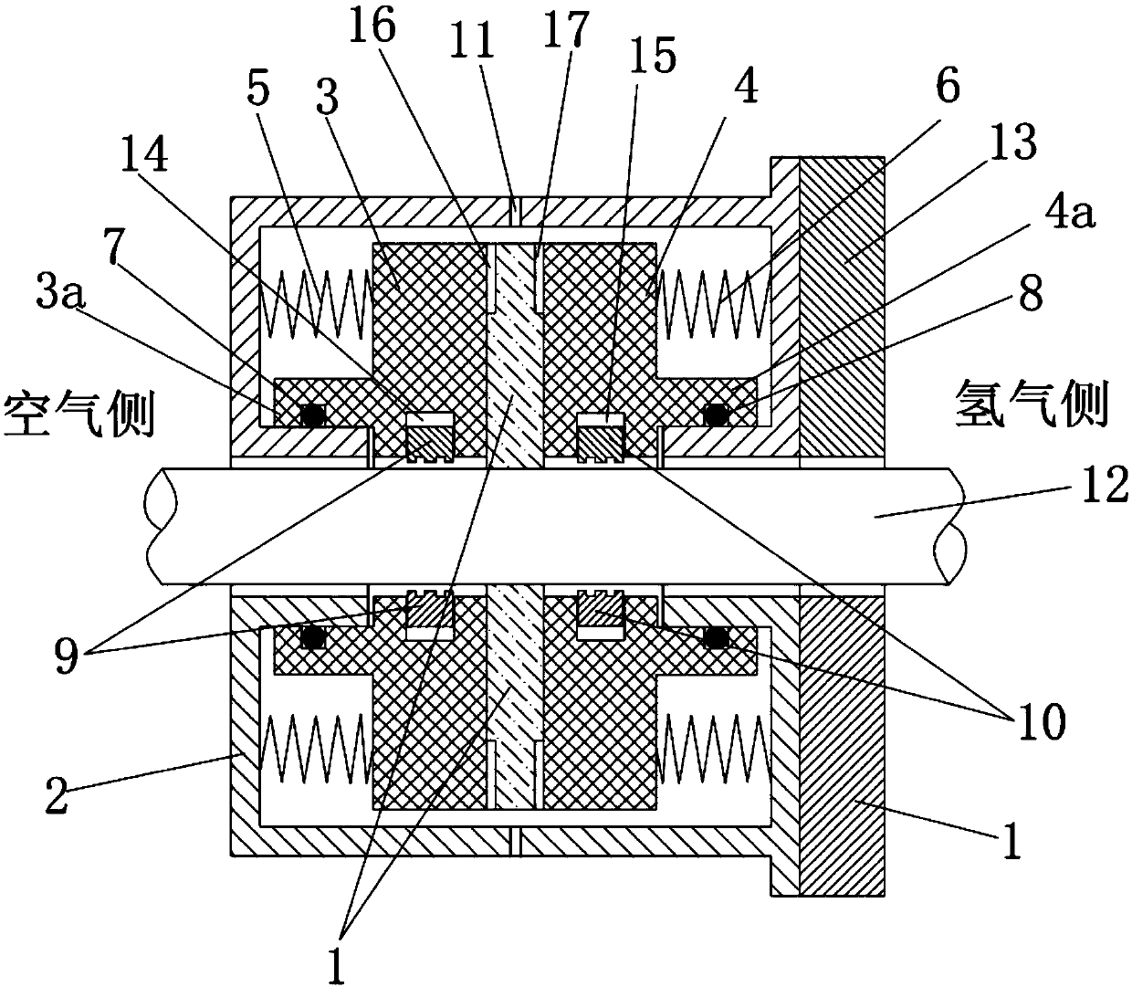
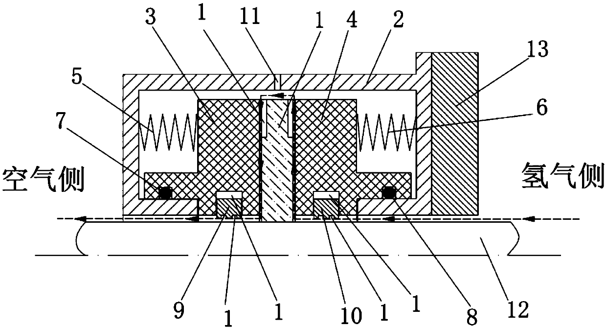
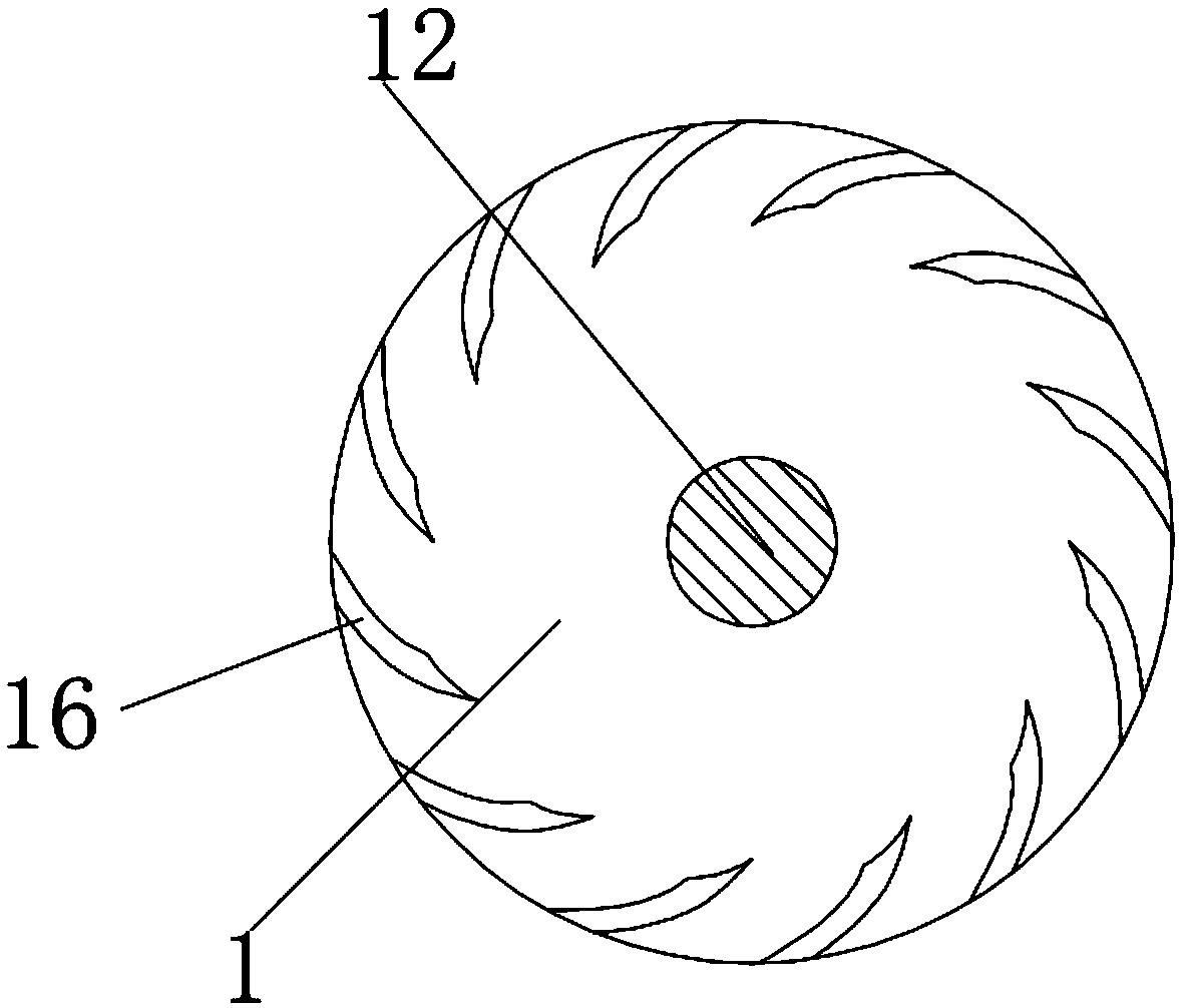
[0021] Depend on Figure 1-6 Given, a hydrogen sealing device for a turbogenerator set in the present invention includes a generator shaft 12 and a generator end cover 13 arranged outside the generator shaft, the generator end cover 13 is a stationary part, and the generator shaft 12 is a rotating part , the generator shaft 12 passes through the generator end cover 13 and can rotate around its axis. There is a certain gap between the two to ensure that the generator shaft 12 does not contact the generator end cover 13 when rotating. The outer side of the generator shaft 12 A seal seat 2 fixed with the generator end cover 13 is provided. The seal seat 2 is a hollow structure with an opening facing the inner side of the generator shaft. The generator shaft 12 at the opening of the seal seat 2 is covered with a Together wi...


PUM


Abstract

The invention relates to a hydrogen sealing device and a sealing method for a steam turbine generator set. According to the technical scheme, a generator rotating shaft at the opening of a sealing seat is sleeved with a resistance disc which is fixed together with the generator rotating shaft, and the resistance disc extends into the inner cavity of the sealing seat from the opening of the sealingseat; a first sealing ring and a second sealing ring which slide left and right in the axial direction of the the generator rotating shaft are arranged in the sealing seat on the two sides of the resistance disc correspondingly, a plurality of first spiral grooves which are uniformly distributed are formed in the outer periphery, right opposite to the first sealing ring, of the resistance disc; and a plurality of second spiral grooves which are uniformly distributed are formed in the outer periphery, right opposite to the second sealing ring, of the resistance disc. Compared with the prior art, two-stage spiral groove type dynamic pressure oil film seal between the sealing rings and the resistance disc and two-stage groove type dynamic pressure oil film seal between sealing floating ringsand the generator rotating shaft are required during hydrogen leakage, and the leakage amount is small; and sealing gaps formed between the sealing rings and the resistance disc due to the dynamic pressure effect of the spiral grooves are small, and therefore the leakage can be effectively reduced.

Description

technical field [0001] The invention relates to a sealing method between the dynamic and static parts at both ends of a hydrogen-cooled turbogenerator, which reduces the leakage of hydrogen along the shaft end and the resulting harm to the safe operation of the unit, and is mainly used for hydrogen-cooled generators. seal. Background technique [0002] With the increase of the unit capacity of the generator set, the heat generated during the operation of the generator increases. In order to improve the cooling effect, hydrogen is generally used as the cooling medium in large generator sets to replace water or air. There is a gap between the moving and static parts of the generator, and hydrogen will leak along the gap between the two. Hydrogen is a flammable and explosive gas. When its concentration in the air reaches a certain level, it will cause an explosion, which will cause great harm to the safe operation of the unit and the lives of personnel. Therefore, hydrogen l...

Claims


Application Information

Patent Timeline
Patent Type & Authority Applications(China)
IPC IPC(8): F16J15/40
Inventor 张文涛夏亚磊李勇
Owner CENT CHINA BRANCH OF CHINA DATANG CORP SCI & TECH RES INST CO LTD
Why Eureka
Try Eureka