IGBT junction temperature thermal calculation method under fault current

A fault current and thermal calculation technology, applied in the field of thermal calculation, can solve problems such as unsuitable relationship between transient disturbance current and temperature rise, and achieve the effects of shortening calculation time, accurate prediction results, and high precision

Inactive Publication Date: 2018-10-19
ZHOUSHAN ELECTRIC POWER SUPPLY COMPANY OF STATE GRID ZHEJIANG ELECTRIC POWER +2
View PDF5 Cites 16 Cited by
  • Summary
  • Abstract
  • Description
  • Claims
  • Application Information

AI Technical Summary

Problems solved by technology

At the same time, the thermal network model of IGBT realizes the calculation of IGBT junction temperature under short-circuit fault, but this method also has limitations, and it is not suitable for studying the relationship between tran

Method used


Image

  • IGBT junction temperature thermal calculation method under fault current
  • IGBT junction temperature thermal calculation method under fault current
  • IGBT junction temperature thermal calculation method under fault current

Examples


Embodiment Construction

[0045] The technical solution of the present invention will be further described in detail below in conjunction with the accompanying drawings.

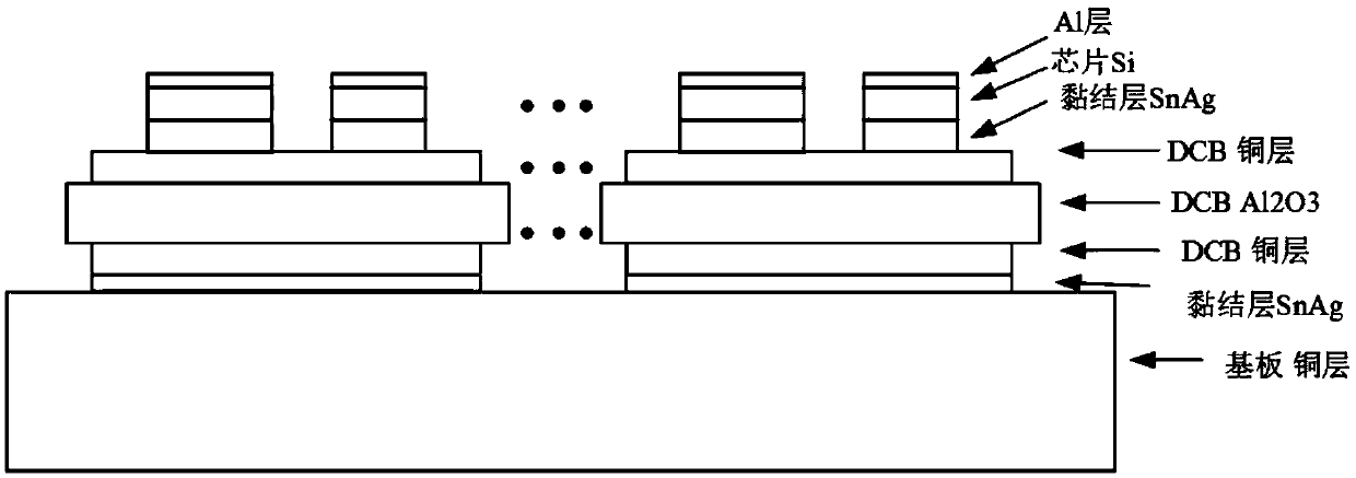
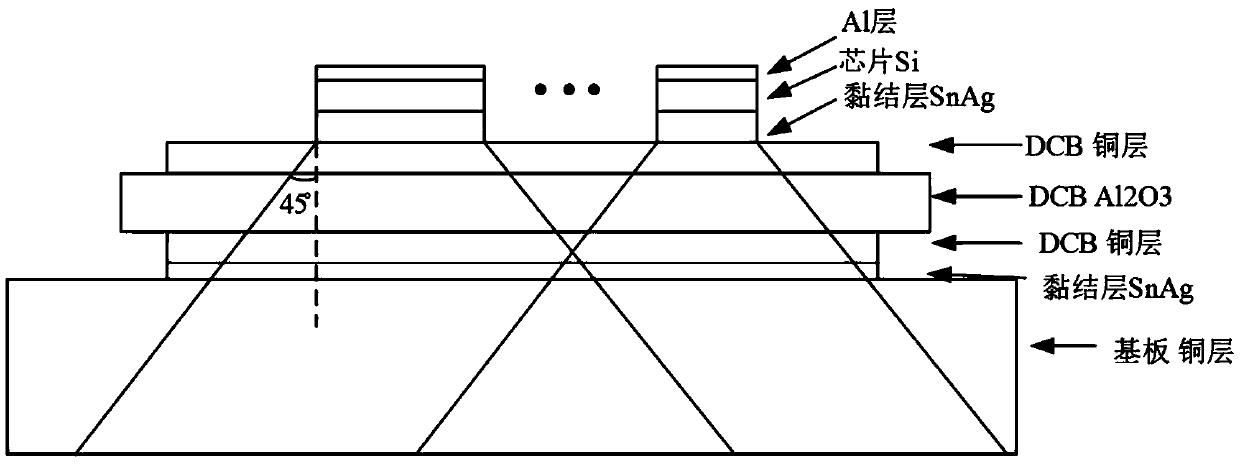
[0046] The present invention studies the actual packaged IGBT module of FF300R12ME4, the internal structure diagram is as follows figure 1 shown. The module contains six 10.4mm×9.4mm IGBT chips and six 7.2mm×7.2mm diode chips (FRD), with a substrate size of 119.0mm×58.8mm. The chip is 0.3mm thick, the substrate solder is 0.2mm thick, the copper layer 1 is 0.3mm thick, the Al2O3 liner is 1mm thick, the copper layer 2 is 0.25mm thick, the substrate solder is 0.2mm thick, and the substrate is 5mm thick.

[0047] In conjunction with specific embodiments, the thermal calculation method based on the IGBT junction temperature under the fault current includes the following steps:

[0048] A. Calculate power module loss according to the circuit state information and the loss parameter.

[0049] A1. First consider the conduction loss. In t...


PUM


Abstract

An IGBT junction temperature thermal calculation method under a fault current relates to a thermal calculation method, and aims to solve the technical problems that an existing method cannot effectively reflect the transient junction temperature of each chip in an IGBT module; the method comprises the following steps: 1, calculating power module loss according to circuit state information and a loss parameter, fitting a manual curve of the IGBT module so as to obtain a conduction voltage drop, an IGBT open loss and a shut down loss, and using an instantaneous power consumption integration in aperiod to represent the loss; 2, obtaining a power device peak junction temperature calculation method under a burst pulse power according to an IGBT peak junction temperature calculation method under a short power pulse, inputting IGBT module thermal property parameters, using the physical parameter of a related layer to simulate a thermal response curve in operation, and building a module system thermal circuit module; 3, determining the IGBT module temperature. The IGBT junction temperature thermal calculation method is reasonable in design, high in precision, and accurate in prediction results.

Description

technical field [0001] The invention relates to a thermal calculation method, in particular to a thermal calculation method based on IGBT junction temperature under fault current. Background technique [0002] According to the research report on the reliability of power electronic systems, power semiconductor devices are the core components of modern power electronic conversion devices, and they are also the components with the highest failure rate in the converter system, accounting for about 34%. Among various failure factors, about 55% of power electronic system failures are mainly induced by temperature factors. Therefore, in order to avoid severe performance degradation or even catastrophic damage of the power module, the maximum operating junction temperature and the junction temperature fluctuation of the power module should be closely monitored. Specifically, the thermal breakdown failure and thermal fatigue failure of the module are triggered by its highest operati...

Claims


Application Information

Patent Timeline
IPC IPC(8): G01R31/26
CPCG01R31/2601
Inventor 戴涛刘黎姚晖乔敏袁杰李剑波俞兴伟卢志飞杨勇詹志雄许琤刘懿胡晶格黄萌孙建军
Owner ZHOUSHAN ELECTRIC POWER SUPPLY COMPANY OF STATE GRID ZHEJIANG ELECTRIC POWER
Why Eureka
Try Eureka