Automatic film covering equipment for plates

A technology for plate and lamination, applied in the field of automatic lamination equipment for plates, can solve the problems of poor lamination quality, low efficiency, bubbling, etc., to achieve high production efficiency, improve quality, and avoid damage to plates.

Pending Publication Date: 2018-10-23
CHANGZHOU INST OF LIGHT IND TECH
View PDF8 Cites 15 Cited by
  • Summary
  • Abstract
  • Description
  • Claims
  • Application Information

AI Technical Summary

Problems solved by technology

[0003] There are many types of laminating machines, and the laminating action of the product is generally completed by pressing two smooth rollers, and most of the existing laminating machines are suitable for the laminating operation of continuous boards, block boards The parts are in the lamination process, the boards are easy to slide, and the lamination close to the two smooth rollers is prone to bubbling, wrinkling, etc. The quality of the lamination film is poor, and after the lamination is completed, manual or other equipment is required to trim the excess film Shaping operation, low production efficiency

Method used


Image

  • Automatic film covering equipment for plates
  • Automatic film covering equipment for plates
  • Automatic film covering equipment for plates

Examples


Embodiment 1

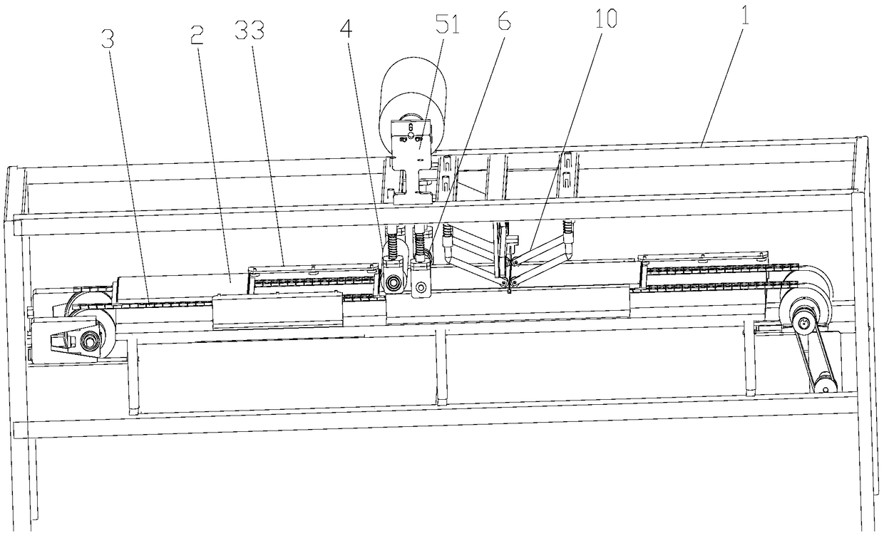
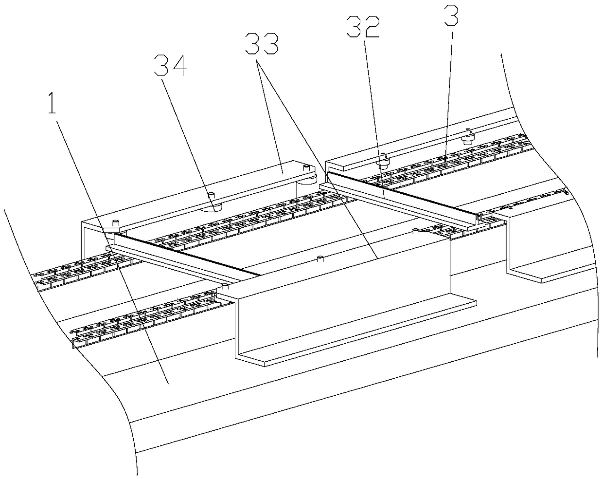
[0025] Embodiment 1: refer to figure 1 , figure 2 , plate automatic coating equipment, including frame 1, a transmission mechanism for transmitting plate 2 on frame 1, and a film coating mechanism for coating plate 2 on the transmission mechanism. The transmission mechanism includes a frame along the length of frame 1 The conveyor belt 3 and the conveyor roller 31 arranged in the direction, the conveyor roller 31 is arranged on the front and rear ends of the frame 1, the conveyor belt 3 is wound on the conveyor roller 31, the frame 1 is provided with a motor that drives the conveyor roller 31 to rotate, and the motor passes through the chain. The wheel transmission mechanism is connected with one of the transmission rollers 31. The output end of the motor is provided with a driving runner, and one end of the transmission roller is provided with a driven runner. The driving runner and the driven runner are connected by a chain, and the motor drives the conveyor belt 3 to rotat...

Embodiment 2

[0030] Embodiment 2: refer to figure 1 , figure 2 , plate automatic coating equipment, including frame 1, a transmission mechanism for transmitting plate 2 on frame 1, and a film coating mechanism for coating plate 2 on the transmission mechanism. The transmission mechanism includes a frame along the length of frame 1 The conveyor belt 3 and the conveyor roller 31 arranged in the direction, the conveyor roller 31 is arranged on the front and rear ends of the frame 1, the conveyor belt 3 is wound on the conveyor roller 31, the frame 1 is provided with a motor that drives the conveyor roller 31 to rotate, and the motor passes through the chain. The wheel transmission mechanism is connected with one of the transmission rollers 31. The output end of the motor is provided with a driving runner, and one end of the transmission roller is provided with a driven runner. The driving runner and the driven runner are connected by a chain, and the motor drives the conveyor belt 3 to rotat...


PUM


Abstract

The invention relates to the technical field of film covering machines, in particular to automatic film covering equipment for plates. The automatic film covering equipment for the plates comprises arack, a conveying mechanism and a film covering mechanism, wherein the conveying mechanism conveys the plates on the rack and comprises a conveying belt and conveying rolls; the conveying belt is wound on the conveying rolls; a positioning baffle for positioning the front-back directions of the plates is arranged on the conveying belt; a guiding plate for limiting the left-right position of the plates is arranged on the rack; the film covering mechanism comprises a pressing and covering roll and a film supply assembly on the upper portion of the pressing and covering roll; the pressing and covering roll is movably connected with the rack; a pressure adjusting mechanism for adjusting downward pressure of the pressing and covering roll is arranged on the rack; a shaping roll is arranged on the rear side of the pressing and covering roll; disc hobs for cutting residual thin films are arranged on the shaping roll and correspond to the left sides and the right sides of the plates; side surface pressing rolls which press and cover the guiding plate are arranged at the position, which corresponds to the guiding plate, of the shaping roll; and a cutting assembly is arranged on the rear side of the shaping roll. Continuous film covering production of blocky plates is realized, after film covering, residual films are cut off and shaped immediately, the film covering quality is improved,and the production efficiency is high.

Description

technical field [0001] The invention relates to the technical field of laminating machines, in particular to automatic laminating equipment for plates. Background technique [0002] At present, the competition of consumer products in the electronics and electrical appliances industry is very fierce. In order to occupy the market and realize product value, the appearance of the product has become an important factor. Since the product shell parts may come into contact with external objects during production, processing and assembly, as well as product inspection and handling, it may cause slight scratches, scratches, dirt and other defects on the surface, which will affect the appearance quality of the product. Therefore, it has become a necessary link to protect the surface of the product shell parts, and the surface protection film is a commonly used protection process. Laminating is usually carried out by a laminating machine, for example, to protect liquid crystal panels...

Claims


Application Information

Patent Timeline
Patent Type & Authority Applications(China)
IPC IPC(8): B32B37/10B32B38/04B32B37/00
CPCB32B37/003B32B37/10B32B38/04B32B2038/045
Inventor 高晓宇
Owner CHANGZHOU INST OF LIGHT IND TECH
Why Eureka
Try Eureka