
A parameter optimization method of an anti-offset constant current output wireless power transmission device

A technology of wireless power transmission and constant current output, applied in circuit devices, battery circuit devices, transportation and packaging, etc., can solve problems such as unstable output current, and achieve the effect of expanding the range, expanding the offset range, and ensuring the optimization effect.

Active Publication Date: 2021-05-28
SOUTHWEST JIAOTONG UNIV
View PDF4 Cites 1 Cited by
  • Summary
  • Abstract
  • Description
  • Claims
  • Application Information

AI Technical Summary

Problems solved by technology

[0004] The purpose of the present invention is: the present invention provides a parameter optimization method of an anti-offset constant current output wireless power transmission device, which solves the problem of unstable output current caused by coil offset in existing wireless power transmission devices

Method used


Image

  • A parameter optimization method of an anti-offset constant current output wireless power transmission device
  • A parameter optimization method of an anti-offset constant current output wireless power transmission device
  • A parameter optimization method of an anti-offset constant current output wireless power transmission device

Examples


Embodiment 1

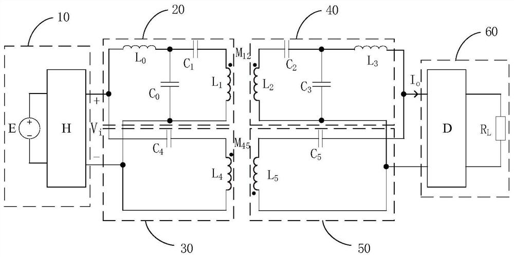
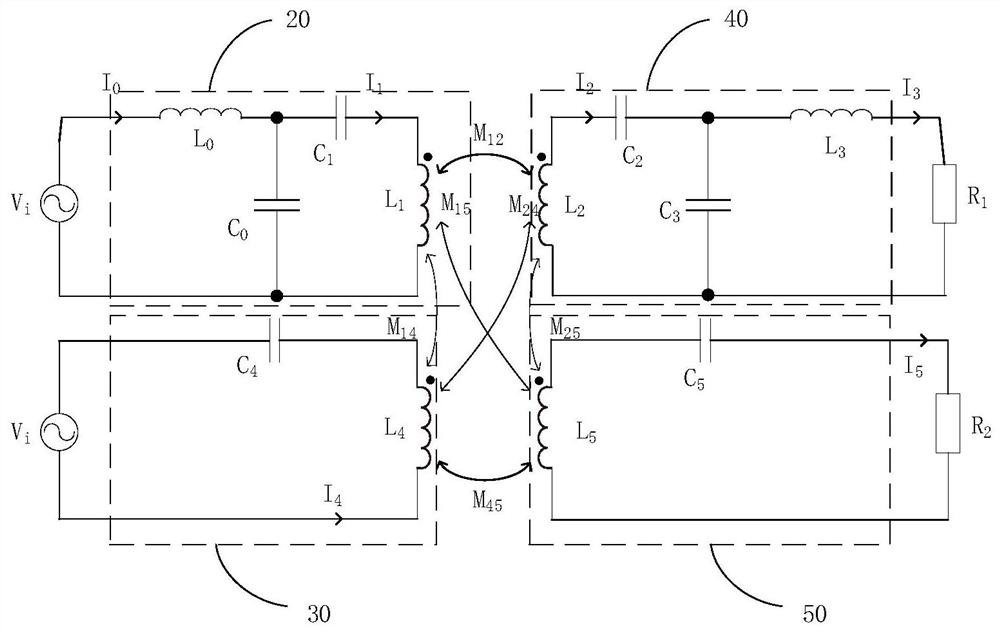
[0048] see Figure 2-3 , the anti-offset constant current output wireless power transmission system of the present invention is used to realize the wireless power transmission between the primary side and the secondary side in the system. The anti-offset constant current output wireless power transmission system includes a front-end module 10, The first sending module 20 connected to the front-end module, the second sending module 30 connected to the front-end module 10, the first receiving module 40 coupled to the first sending module 20, the second receiving module coupled to the second sending module 30 Module 50, and the post-stage module 60 that is connected with the first receiving module 40, the second receiving module 50; The first sending module 20, the second sending module 30, the first receiving module 40, the second receiving module 50, and the second The components of the receiving module 50 are set according to the requirements, and the first transmitting module...

Embodiment 2

[0088] Such as Figure 7 As shown, including the control circuit and the main circuit of the inverter, the control signal of the inverter uses the PWM signal generated by DSP, and the model of DSP adopts TMS320F28335. The topological structure of the main circuit has the characteristics: the mutual inductance changes, and the corresponding two parallel branch output current expressions in Relative changes and mutual superposition, by optimizing the parameters, when the mutual inductance changes in the -5%-5% interval, the two The sum is almost a constant value, and the system can still output a current that has nothing to do with the load when the offset is realized, that is, the anti-offset constant current output is realized, and the offset range is expanded at the same time, which solves the problem of the output caused by the coil offset of the existing wireless power transmission device. The problem of current instability has achieved the effect of ensuring constant cu...


PUM


Abstract

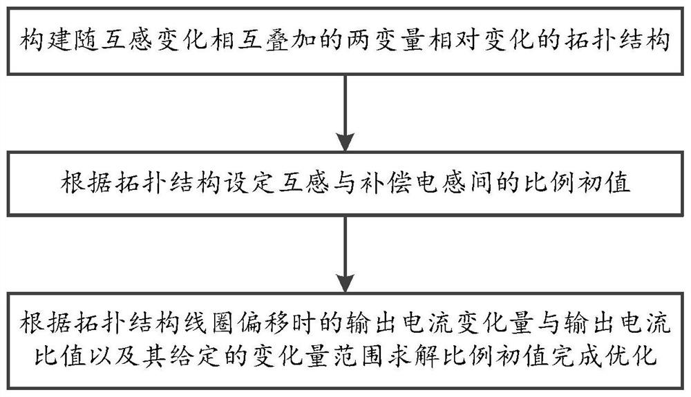
The invention discloses a parameter optimization method of an anti-offset constant current output wireless power transmission device, which relates to the field of wireless charging; it includes the following step 1: constructing a topology structure of relative changes in two variables superimposed with changes in mutual inductance; step 2: Set the initial value of the ratio between the mutual inductance and the compensation inductance according to the topology; Step 3: According to the ratio of the output current variation and the output current when the topology coil is offset and its given variation range, the initial value of the ratio is calculated to complete the optimization; The invention solves the problem of unstable output current caused by coil offset in the existing wireless energy transmission device, and achieves the effect of ensuring constant current output when the coil is offset during the wireless energy transmission process.

Description

technical field [0001] The invention relates to the field of wireless charging, in particular to a parameter optimization method of an anti-offset constant current output wireless power transmission device. Background technique [0002] Wireless power transmission technology transmits energy from the power supply end to the load end in the form of non-electrical contact. High-efficiency technical advantages have been practically applied in many fields such as portable electronic equipment, household appliances, and biomedicine. In recent years, research has gradually been carried out in application fields with high power levels and mobile power supply requirements such as electric vehicles and rail transit. . [0003] The main composition and working process of the existing electric vehicle inductive charging system are as follows: single-phase or three-phase power frequency power is rectified and converted into DC power, and the high-frequency inverter converts the DC powe...

Claims


Application Information

Patent Timeline
Patent Type & Authority Patents(China)
IPC IPC(8): H02J7/02H02J50/12H02J50/40H02J5/00
CPCH02J5/005H02J7/025H02J50/12H02J50/40
Inventor 李砚玲杜浩何正友麦瑞坤
Owner SOUTHWEST JIAOTONG UNIV
Learn More