Topological structure circuit for linearly improving voltage gain of long-distance wireless power transmission and parameter design method
A technology of wireless power transmission and topology structure, applied in circuit devices, electrical components, etc., can solve problems such as inability to meet system output voltage requirements and low voltage gain
- Summary
- Abstract
- Description
- Claims
- Application Information
AI Technical Summary
Problems solved by technology
Method used
Image


Examples
Embodiment 1
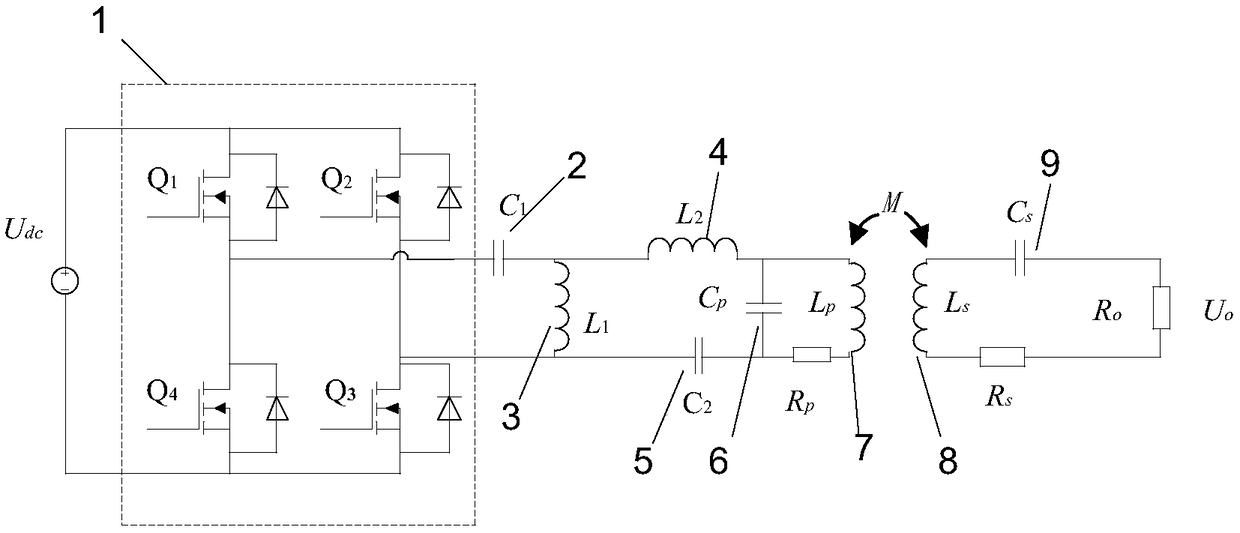
[0031] A topology circuit for linearly increasing the voltage gain of long-distance wireless power transfer, such as figure 1 As shown, the topology circuit includes a primary side resonant compensation network and a secondary side series compensation network; the primary side resonant compensation network includes a full-bridge inverter circuit 1, a resonant compensation network capacitor-2, a resonant compensation network inductance-3, Resonance compensation network inductor two 4, resonance compensation network capacitor two 5, parallel capacitor 6 and primary side transmitting coil 7; the output end of the full-bridge inverter circuit is connected to the resonance compensation network capacitor one 2 and the resonance compensation network inductor one 3 in series; the two ends of the resonance compensation network inductance one 3 are connected in parallel with the series structure of the resonance compensation network inductance two 4, the resonance compensation network ca...
Embodiment 2
[0034] A parameter design method of the topological structure circuit, the parameter design method comprising:
[0035] Step 1: Obtain the series compensation capacitor C according to the inverter switching angular frequency model S and parallel capacitor C P The capacitance value of , where the inverter switching angular frequency model is:
[0036]
[0037] In the model, ω is the switching angular frequency of the inverter, L P Indicates the self-inductance of the transmitting coil of the system, C P Expressed as a compensation capacitor that forms a series resonance with the transmitting coil, L S Indicates the self-inductance of the receiving coil of the system, C S Expressed as a compensation capacitor that forms a series resonance with the receiving coil;
[0038] Step 2: Determine the basic relationship between the compensation components according to the network structure of the topology circuit, wherein the model of the basic relationship is:
[0039]
[0...
Embodiment 3
[0050] This embodiment proposes a topology circuit for linearly increasing the voltage gain of long-distance wireless power transmission, the topology circuit structure is as follows figure 1 As shown, the primary side uses a new type of resonant compensation network, and the secondary side uses series compensation. figure 1 in, U dc is the DC bus voltage of the inverter circuit, Q 1 , Q 2 , Q 3 , Q 4 Form a full bridge inverter circuit. The primary side consists of the transmitting coil L P , parallel capacitance C P , and by L 1 , C 1 , L 2 and C 2 A new type of impedance compensation network composed of R P is the internal resistance of the transmitting coil. L s is the receiving coil, C s is the series capacitance, R s is the resistance of the receiving coil. M is the mutual inductance between the transmitting coil and the receiving coil, where k is the coupling coefficient.
[0051] The reactance relationship between parameters in the topology is shown ...
PUM
 Abstract
Description
Claims
Application Information
 - R&D
- Intellectual Property
- Life Sciences
- Materials
- Tech Scout
- Unparalleled Data Quality
- Higher Quality Content
- 60% Fewer Hallucinations
Browse by: Latest US Patents, China's latest patents, Technical Efficacy Thesaurus, Application Domain, Technology Topic, Popular Technical Reports.
© 2025 PatSnap. All rights reserved.Legal|Privacy policy|Modern Slavery Act Transparency Statement|Sitemap|About US| Contact US: help@patsnap.com