Variable stiffness flexible actuator

A flexible driver and variable stiffness technology, applied in the direction of manipulators, manufacturing tools, joints, etc., can solve the problems of small adjustment range, insufficient compactness of driving elements and transmission mechanisms, complex joint structure, etc., and achieve simple control and good flexible dynamic characteristics , good impact resistance effect

Inactive Publication Date: 2018-10-30
TSINGHUA UNIV
View PDF10 Cites 11 Cited by
  • Summary
  • Abstract
  • Description
  • Claims
  • Application Information

AI Technical Summary

Problems solved by technology

[0005] In view of the above problems, the object of the present invention is to provide a variable stiffness flexible driver to solve the problems of complex joint structure, insufficient compactness of driving elements and transmission mechanisms, and small adjustment range in the existing variable stiffness flexible driver, thereby improving the energy efficiency of the robot, system Dynamic characteristics and stability and safety of operation

Method used


Image

  • Variable stiffness flexible actuator
  • Variable stiffness flexible actuator
  • Variable stiffness flexible actuator

Examples


Embodiment 1

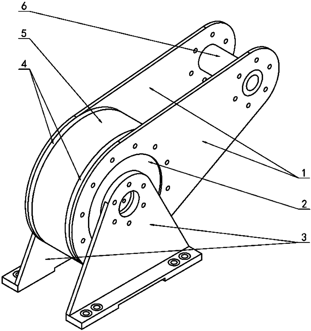
[0032] Combine below Figure 1-Figure 5 Embodiment 1 will be described in detail.

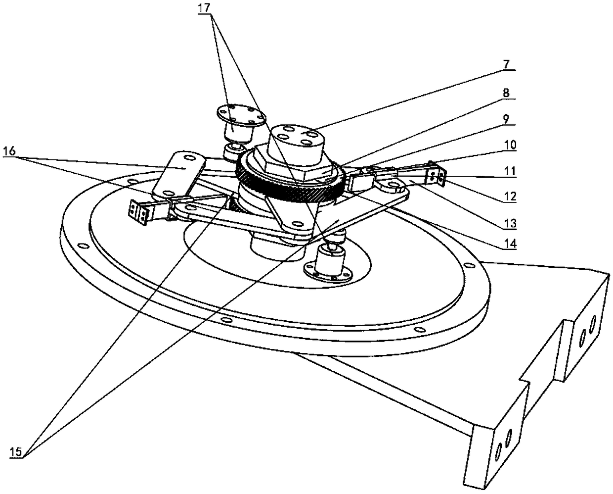
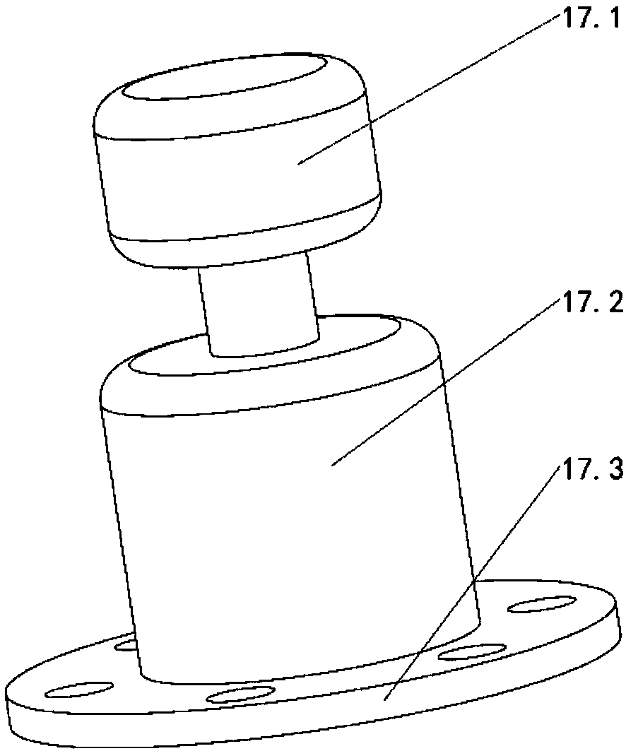
[0033] figure 1 It is a schematic diagram of the three-dimensional structure of the variable stiffness flexible driver described in the present invention, figure 2 It is a schematic diagram of the internal structure of an embodiment of the variable stiffness flexible actuator of the present invention, image 3 for figure 2 The schematic diagram of the structure of the variable stiffness flexible drive motor shown in , such as Figure 1-Figure 3 As shown, the variable stiffness flexible driver of the present invention includes a power transmission mechanism, a stiffness adjustment mechanism and a stiffness output mechanism, wherein the power transmission mechanism includes a gear transmission mechanism and two motors 17, and the two motors 17 are arranged in parallel, and each motor 17 includes a motor base 17.3, a motor main body 17.2 and a motor output shaft 17.1, and the power is input ...

Embodiment 2

[0042] Combine below Figure 6-Figure 9 This embodiment will be described in detail.

[0043] Figure 6 It is a schematic diagram of the internal structure of another embodiment of the variable stiffness flexible actuator of the present invention,

[0044] Figure 7 for Figure 6 The structural diagram of the stiffness adjustment mechanism of the variable stiffness flexible actuator shown in , such as Figure 6-Figure 7 As shown, the variable stiffness flexible driver of the present invention includes a power transmission mechanism, a stiffness adjustment mechanism and a stiffness output mechanism, wherein the power transmission mechanism includes a gear transmission mechanism and two motors 17, and the two motors 17 are arranged in parallel, and each motor 17 includes a motor base 17.3, a motor main body 17.2 and a motor output shaft 17.1, and the power is input to the gear transmission mechanism through the motor 17; the stiffness adjustment mechanism includes two four-b...


PUM


Abstract

The invention discloses a variable stiffness flexible actuator. The variable stiffness flexible actuator comprises a power transmission mechanism, a stiffness adjusting mechanism and a stiffness output mechanism; the power transmission mechanism comprises a gear transmission mechanism and two motors, the two motors are arranged in parallel connection, and the gear transmission mechanism inputs power; the stiffness adjusting mechanism comprises two four-rod mechanisms, each four-rod mechanism comprises a first connecting rod, a second connecting rod, a third connecting rod and a plate spring, and a sliding block is arranged on the plate spring; the stiffness output mechanism comprises a stiffness output shaft, a pair of stiffness output rods, a shell and a support, and through two motors, the balance position of output of the stiffness output mechanism and the position of the sliding block on the plate spring are controlled, and therefore stiffness of the variable stiffness flexible actuator is adjusted; through dual-plate-spring dual four-rod mechanisms, the stiffness control range of the actuator is larger, the structure is compact, the size is small, and control is easy.

Description

technical field [0001] The invention relates to the technical field of flexible drives, in particular to a variable stiffness flexible drive. Background technique [0002] With the rapid development of artificial intelligence software technology, robot research has also entered a new stage. People have higher and higher requirements for mechanical control of service robots, bionic robots and rehabilitation robots, and the speed and safety of control need to be further improved. [0003] In the field of service robots, bionic robots, and rehabilitation robots, the joints of robots need a certain degree of compliance, and the increase in compliance can not only improve energy efficiency, but also improve the dynamic characteristics of the system. The flexible drive changes rigid output into flexible output by introducing elastic elements into the transmission mechanism. [0004] The characteristic of the flexible output is that the elastic element can store and release energy...

Claims


Application Information

Patent Timeline
Patent Type & Authority Applications(China)
IPC IPC(8): B25J17/02
CPCB25J17/0208B25J17/0258
Inventor 吴军陈代伟张彬彬付鹏
Owner TSINGHUA UNIV
Why Eureka
Try Eureka